IPM490 / IPM500
SERIAL COMMUNICATIONS MANUAL
For Series 2 Digital Meters
Custom ASCII protocol
10 Thomas, Irvine, CA 92618, USA Tel: (949) 465-09001
••••
Fax: (949) 465-0905
Website: www.futek.com
Страница 1: ...IPM490 IPM500 SERIAL COMMUNICATIONS MANUAL For Series 2 Digital Meters Custom ASCII protocol 10 Thomas Irvine CA 92618 USA Tel 949 465 09001 Fax 949 465 0905 Website www futek com...
Страница 2: ...multipoint or multidrop communi cations with addressing of up to 31 devices on the same RS485 serial data line Digital panel meters counters and timers require a plug in option board for serial commun...
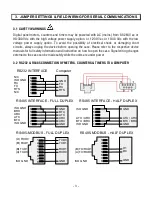
Страница 3: ...fety information and instruction on how to open the case Signal wiring changes external to the case can be made safely while the units are under power 3 2 RS232 RS485 CONNECTION OF METERS COUNTERS TIM...
Страница 4: ...and j installed RS485 and RS485 Modbus Boards Full Duplex Operation b e These bias jumpers should be installed on 1 and only 1 meter a d Installed on last meter in line with long cable runs Half Dupl...
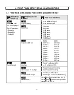
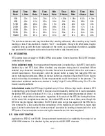
Страница 5: ...19200 baud __000U Output update rate 60 Hz 50 Hz 0 0 017 sec 0 020 sec 1 0 28 sec 0 34 sec 2 0 57 sec 0 68 sec 3 1 1 sec 1 4 sec 4 2 3 sec 2 7 sec 5 4 5 sec 5 4 sec 6 9 1 sec 10 9 sec 7 18 1 sec 21 8...
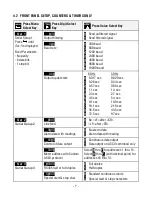
Страница 6: ...end of each item 00000U Data sent digital panel meter only 0 Reading 1 Peak 2 Valley 3 Reading Peak 4 Reading Valley 5 Reading Peak Valley 00000U Data sent scale meter only 0 Net Gross 1 Net only 2 Gr...
Страница 7: ...3 1 1 sec 1 4 sec 4 2 3 sec 2 7 sec 5 4 5 sec 5 4 sec 6 9 1 sec 10 9 sec 7 18 1 sec 21 8 sec 8 36 6 sec 43 5 sec 9 72 5 sec 97 sec Ser 2 Serial Setup 2 __0000U Line feed 0 No LF after CR 1 LF after CR...
Страница 8: ...mode 0 All active items 1 Item 1 only 2 Item 2 only if active 3 Item 3 only if active 4 Peak only 5 Displayed item 6 Valley only 7 All active items Peak Ser 4 Serial Setup 4 ___000U Modbus ASCII gap...
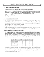
Страница 9: ...ive the measurement data may require a line feed character LF following the CR The line feed character LF may be selected in Ser 2 Adding a Coded Data Character to the Basic Format It is possible to a...
Страница 10: ...st device should have a termination resistor installed It is necessary to set up each device on the bus with a different address from 1 to 31 To command a particular device its address is used in conj...
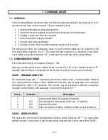
Страница 11: ...accordingly Output Rate Data Output Rate Minimum Baud Rate Ser 1 Setting 50 Hz 60 Hz 1 Item Sent 2 Items Sent 3 Items Sent 0 1 2 3 4 5 6 7 8 9 021s 018 s 34 s 0 28 s 68 s 0 57 s 1 4 s 1 1 s 2 7 s 2 3...
Страница 12: ...ive buffer is nearly full takes the RTS line low to halt data transmission When its receive buffer has emptied it takes the RTS line high to enable more data transmissions Some measurements could be m...
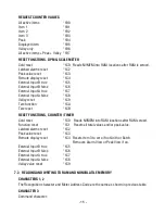
Страница 13: ...ormat is 4 characters Example 5A1 After any command that causes a Meter Reset such as C0 F W X the Counter sends an R character after the Reset is complete and the Counter is ready to accept a new com...
Страница 14: ...xamples below use a default address of 1 following the Substitute the desired address from the above table of Serial Comm Address Codes All command sequences shown must terminate with CR followed by a...
Страница 15: ...e function 1CA Tare reset 1CB RESET FUNCTIONS COUNTER TIMER Cold reset 1C0 Reads NVMEM into RAM locations after RAM zeroed Function reset 1C1 Resets all total values and or peak value Latched alarms r...
Страница 16: ...a continuous string of bytes consisting of 2 hex characters 0 9 A F per byte Included in the command are the total number of bytes to be transferred and the most significant address in RAM of the con...
Страница 17: ...OR REMOTE DISPLAY OPERATION OF DPM OVERVIEW A DPM can serve as a remote display that responds to values sent via serial communications by a PC or by another DPM in a Master Slave configuration In one...
Страница 18: ...M d Front panel pushbuttons RESET and MENU are simultaneously pushed to cause a Cold Reset of the DPM Notes After the Remote Display value is entered the DPM can be put back in the Continuous mode wit...
Страница 19: ...Counter has 13 Display Modes 0 12 Modes 0 5 are normal measurement modes Modes 6 12 are dedicated to Remote Display without making any normal readings In any of the 13 modes remote display data may be...
Страница 20: ...n the H K L commands may or may not include a coded Alarm character If included this character always overrides the internal Alarm comparisons and determines the alarm indicators the relay operation a...
Страница 21: ...e setting for which there is no serial communication with the meter It is suggested to use CONFIG 6XXX to set the following parameters and then to use CONFIG CXXX for operation 1 START character set t...
Страница 22: ...D START AND STOP CHARACTERS The meter recognizes an asterisk as the command recognition character In the counter another command recognition character may be chosen to make the meter compatible with a...
Страница 23: ...button tares the meter 0 0 0 Not rate 0 0 1 Rate x 0 1 0 1 0 Rate x 1 0 1 1 Rate x 10 1 0 0 Rate x 100 1 0 1 Rate x 1000 1 1 0 Rate x 10 000 BF L Analog Setup Bit 7 6 5 4 3 2 1 0 0 Analog output unfi...
Страница 24: ...point programming 1 Alarm setup 1 Front panel DPM reset 1 Front panel Peak Alarm reset 1 View alarm setpoints 1 View Peak value Tare function 33 L Lockout1 0 unlocked 1 locked Bit 7 6 5 4 3 2 1 0 Menu...
Страница 25: ...0 0 300 baud 0 0 1 600 baud 0 1 0 1200 baud 0 1 1 2400 baud 1 0 0 4800 baud 1 0 1 9600 baud 1 1 0 19200 baud 0 Send unfiltered value 1 Send filtered value 2F L Filter Bit 7 6 5 4 3 2 1 0 0 0 0 0 Auto...
Страница 26: ...1 0 1 Tare Reset 1 1 0 External Decimal Point 1 1 1 1 External Decimal Point 2 1 Coordinates of 2 points for Scale Offset 0 Scale and Offset direct parameters 0 Normal Format Ser Com Continuous mode 1...
Страница 27: ...atch Al4 latch 0 0 Relay3 On when Al3 active Relay4 On when Al4 active 0 1 Relay3 Off when Al3 active Relay4 On when Al4 active 1 0 Relay3 On when Al3 active Relay4 Off when Al4 active 1 1 Relay3 Off...
Страница 28: ...2 Off when Al2 active 00 U Serial Cnfg4 NG to review carefully Bit 7 6 5 4 3 2 1 0 Serial Protocol 0 0 No Parity 0 1 Odd Parity 0 0 Custom ASCII protocol 8 bits 0 1 Modbus RTU protocol 8 bits 1 0 Modb...
Страница 29: ...3 72 71 70 6F 6E 18 17 16 15 14 13 12 11 10 0F 0E 0D 0C 0B Setup1 Deviation4 3 Deviation4 1 Deviation3 2 Setpoint4 3 Setpoint4 1 Setpoint3 2 Alarm Cnfg4 Deviation2 3 Deviation2 1 Deviation1 2 Configur...
Страница 30: ...IX B COUNTER TIMER MEMORY ADDRESSES AND DATA DEFINITIONS 9 1 COUNTER TIMER 1 BYTE RAM MEMORY DATA L Lower memory U Upper memory Hex Address Item Name Bit Assignment 43 Resolution Bit 7 6 5 4 3 2 1 0 M...
Страница 31: ...Item 0 1 Item 1 1 0 Item 2 1 1 Item 3 Compare Setpoint 1 to 0 0 Filtered Item 0 1 Item 1 1 0 Item 2 1 1 Item 3 36 Lockout2 0 unlocked 1 locked Bit 7 6 5 4 3 2 1 0 1 Change Item 1 CALib 1 Ser 1 Ser 2...
Страница 32: ...dressable 0 1 1 1 Remote Display Single Value 1 0 0 0 Slave Display 1st data value of string 1 0 0 1 Slave Display 2nd data value of string 1 0 1 0 Slave Display 3rd data value of string 1 0 1 1 Slave...
Страница 33: ...baud 0 1 0 1200 baud 0 1 1 2400 baud 1 0 0 4800 baud 1 0 1 9600 baud 1 1 0 19200 baud 0 Send unfiltered value 1 Send filtered value 30 Options Do not use This byte is determined by installed option b...
Страница 34: ...1 1 Display item 2 Display item 3 0 Scale2 Offset2 entered directly 1 Scale2 Offset2 using Coordinates of 2 points 0 Scale1 Offset1 entered directly 1 Scale1 Offset1 using Coordinates of 2 points 0 Bl...
Страница 35: ...ctive Al2 Hi Active 0 0 0 1 Al1 Lo Active Al2 Hi Active 0 0 1 0 Al1 Disabled Al2 Hi Active 0 1 0 0 Al1 Hi Active Al2 Lo Active 0 1 0 1 Al1 Lo Active Al2 Lo Active 0 1 1 0 Al1 Disabled Al2 Lo Active 1...
Страница 36: ...s always Hysteresis1 Offset 1 Setpoint1 Values stored as sign MS bit magnitude all other bits fixed DP 6 Hex MS Hex Mid Hex LS Name A7 A1 A6 A0 A5 9F Scale2 Scale1 9 4 COUNTER TIMER NON VOLATILE MEMOR...
Страница 37: ...tart Modbus Address Total A Byte 5 Total A Byte 3 Total A Byte 1 Total B Byte 5 Total B Byte 3 Total B Byte 1 Analog Type Cutoff Byte 1 System Decimal Point Resolution Slope Pulses Byte 1 Analog Outpu...
Страница 38: ...ow Reading1 Byte 1 Low Input1 2 Setpoint1 Byte 3 Setpoint1 Byte 1 High Reading2 2 High Input2 Byte 3 High Input2 Byte 1 Low Reading2 Byte 2 Low Input2 Byte 3 Low Input2 Byte 1 High Reading1 Byte 2 Hig...
Страница 39: ...40 Copyright 2001 2015 FUTEK Advanced Sensor Technology Rev 27 October 2015...