FURUNO
FAR-21x7/28x7 SERIES
SP - 2
E3519S01N-M
FAR-2837SW
Ferrite circulator with TR limiter
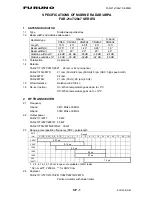
3 MONITOR
UNIT
3.1 Screen
Raster scan, daylight bright, yellow or green echoes in 32 levels
3.2 Display
FAR-21x7 series
FAR-21x7 series
FAR-28x7 series
Model MU-170C
MU-201CR
MU-231CR
Size
17-inch color LCD
20.1-inch color LCD,
23.1-inch color LCD
Display area (mm)
338 x 270
399 x 319
470 x 353
Resolution (pixel)
1280 x 1024
1280 x 1024
1600 x 1200
Effective radar
diameter (mm)
260
(H: 64 kHz; V: 60 Hz)
308
(H: 64 kHz, V: 60 Hz)
340
(H: 75 kHz, V: 60 Hz)
Viewable range
(mm)
920 1080 1200
3.3 Minimum range
22 m
3.4 Range discrimination
26 m
3.5 Range scales (nm), Ring interval
Range (nm)
0.125 0.25
0.5
0.75
1
1.5
2
3
4
6
8
12
Ring interval (nm)
0.025 0.05
0.1
0.25
0.25
0.25
0.5
0.5
1
1
2
2
Number of rings
5
5
5
3
6
6
6
6
4
6
4
6
16 24 32 48 72 96 120
4 4 8 8 12
16 20
4 6 4 6 6 6 6
3.6 Range accuracy
1% of the maximum range of the scale in use or 10m,
whichever is the greater
3.7 Bearing discrimination
0.98° (XN5A), 2.1° (XN12AF), 1.5° (XN20AF), 1.2° (XN24AF),
2.0°
(SN36AF)
3.8 Bearing
accuracy
±1°
3.9 Presentation mode
Head-up, Cursor-gyro, North-up, Course-up,
True Motion (sea or ground stabilization)
3.10 Target tracking (TT)
Auto or Manual acquisition: 100 targets in 0.2-24(32) nm
Auto tracking on all acquired targets
Tracking: 5/10 pts on all target
3.11 AIS
Capacity: 1000 targets, Tracking: 10 pts on all target
Time of vector: Off/30s/1-60 minutes
3.12 Radar map
20,000 pts in radar mode, 6000 pts on IC card in chart mode
3.13 Acquisition zone
2 zones
3.14 Interwitch function
Selectable from menu
4. INTERFACE
4.1 Heading signal
Synchro signal (20-100VDC or 20-135VAC 50/60/400/500Hz) or
Stepper signal (20-100VDC), built-in interface (option) required,
AD-10 format or IEC61162-2
4.2 Speed
log
IEC61162-1
4.3 AIS
IEC61162-2
4.4 Input data sentences
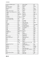
ABK, ACK, ALR, BWC, BWR, DBK, DBS, DBT, DPT, DTM, GGA,
GLL, HDT, MTW, MWV, RMB, RMC, RTE, THS, VBW, VDM, VDO,


