background image

1. RADAR OPERATION 


1-105

1.54 

Sub Monitor (A, B, C and W types) 

The picture from a radar outside the LAN network can be shown on this radar 
(processor unit+display unit+control unit). 
 
1.  Put the cursor in the ANTENNA box at the upper left side of the screen. 
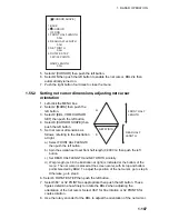
2.  Right-click to show the ANT SELECT menu. 

 [ANT 

SELECT] 

 
ANT1:  

X-BAND 

   12  

FORE


ANT2:  

X-BAND 

   12  

MAIN TOP 

ANT3:          X-BAND

          MAIN  TOP 


     12  


ANT4:          X-BAND
                    AFT


OWN RADAR No.: 2 
 
1 DISP1 

ANT1 


MASTER 

2 DISP2 

ANT2 


MASTER


* Not available on IMO or A radar.

9 STORE INTER-SW
   NO/YES
0 SUB MONITOR*
   OFF/ON

3 DISP3

ANT3
MASTER

4 DISP4

ANT4
MASTER

     12


3.  Spin the scrollwheel to select 0 SUB MONITOR then push the left button. 
4.  Spin the scrollwheel to select ON then push the left button. 

The antenna box shows "SUB" and the image from the sub monitor is shown 
on this radar 

5.  Push the right button to close the menu. 
 
Antenna-related functions of the sub monitor; for example, pulselength, cannot 
be controlled from this radar. 

Содержание FAR-2107(-BB)

Страница 1: ...MARINE RADAR FAR 2807 D Series FAR 2107 BB D Series OPERATOR S MANUAL www furuno co jp MODEL Complies with IMO MSC 192 79...

Страница 2: ...ibutor Dealer 9 52 Ashihara cho Nishinomiya 662 8580 JAPAN Telephone 81 0 798 65 2111 Fax 81 0 798 65 4200 A JAN 2004 Printed in Japan All rights reserved N FEB 04 2011 Pub No OME 35190 N 00017457511...

Страница 3: ...isposal of industrial waste For disposal in the USA see the homepage of the Electronics Industries Alliance http www eiae org for the correct method of disposal How to discard a used battery Some FURU...

Страница 4: ...below Note If the antenna unit is installed at a close distance in front of the wheel house your administration may require halt of transmission within a certain sector of antenna revolution This is...

Страница 5: ...electrical shock or serious injury can result Immediately turn off the power at the ship s mains switchboard if water leaks into the equipment or the equip ment is emitting smoke or fire Continued us...

Страница 6: ...ds Tracking accuracy is affected by the following Tracking accuracy is affected by course change One to two minutes is required to restore vectors to full accuracy after an abrupt course change The ac...

Страница 7: ...speed input 1 23 1 14 Choosing a Range Scale 1 23 1 15 Choosing a Pulselength 1 24 1 15 1 Choosing a pulselength 1 24 1 15 2 Changing pulselength 1 25 1 16 Adjusting the Sensitivity 1 26 1 17 Reducing...

Страница 8: ...es 1 52 1 31 1 Displaying erasing PI lines 1 52 1 31 2 Adjusting PI line orientation PI line interval 1 53 1 31 3 PI line bearing reference 1 53 1 31 4 Maximum number of PI lines to display 1 54 1 31...

Страница 9: ...liance set 1 97 1 50 Reference Position 1 99 1 51 Switching Hub HUB 100 option 1 101 1 52 Anchor Watch 1 102 1 53 Drop Mark 1 103 1 53 1 Activating the drop mark feature 1 103 1 53 2 Inscribing a drop...

Страница 10: ...t and Drift 3 20 3 13 TT Collision Alarm CPA TCPA 3 21 3 13 1 Setting the CPA and TCPA ranges 3 21 3 13 2 Acknowledging the TT collision alarm 3 22 3 14 Acquisition Zone 3 22 3 14 1 Activating an acqu...

Страница 11: ...4 Own Ship s Data 4 21 4 15 Messages 4 22 4 15 1 Creating saving messages 4 22 4 15 2 Transmitting messages 4 23 4 15 3 Viewing messages 4 24 4 16 AIS System Messages 4 26 5 VIDEO PLOTTER OPERATION 5...

Страница 12: ...nav line waypoint mark 5 30 5 12 Recording Data 5 32 5 12 1 Initializing memory RAM cards 5 32 5 12 2 Recording data 5 33 5 13 Replaying Data 5 35 5 14 Deleting Files 5 36 6 MAINTENANCE TROUBLESHOOTI...

Страница 13: ...nd maintained properly Please carefully read and follow the recommended procedures for operation and maintenance We would appreciate hearing from you the end user about whether we are achieving our pu...

Страница 14: ...d required test results Target alarm watches for targets entering or exiting an alarm zone TCPA CPA alarms Electronic parallel index lines 42 rpm antenna for high speed craft Usage Limitations The FAR...

Страница 15: ...state USA ferry Specification type and function availability Type Function IMO A B C W TT symbol selection No No Yes Yes Yes TT w o gyro No No Yes Yes Yes Acquisition zone range limitation Yes No No...

Страница 16: ...rejector Suppress interference transmitted by other radars Interference received simultaneously from many radars can be difficult to reduce 1 25 Echo stretch Enlarge target echoes especially small ec...

Страница 17: ...xv PROGRAM NUMBER PC Board Program No Version No MAIN 035 9204 03 Merchant RFC 035 9202 01 KEY REMOTE 035 9203 01 ARPA 035 9212 01 Minor modification...

Страница 18: ...to weather All other units Protected from weather ANTENNA UNIT Performance Monitor PM 31 built in Rectifier RU 3424 RU 1746B 2 Transformer Unit RU 1803 DC spec AC spec Track Control Unit Memory Card I...

Страница 19: ...z HSC 440 VAC 3 60 Hz HSC FAR 2827W D RSB 103 24 rpm powered by processor unit FAR 2837S D Same as FAR 2137S FAR 2837SW D RSB 104 105 21 26 rpm 200 VAC 3 50 Hz 220 VAC 3 60 Hz 380 VAC 3 50 Hz 440 VAC...

Страница 20: ...her FAR 2117 BB 2127 BB ANTENNA UNIT Performance Monitor PM 31 built in FAR 2117 BB FAR 2127 BB Rectifier RU 3424 RU 1746B 2 Transformer Unit RU 1803 DC spec AC spec VDR External Monitor Alarm Navigat...

Страница 21: ...FAR 2827W D Waveguide For FAR 2827W D Option Dockyard supply Standard Category of Units Antenna unit Exposed to weather All other units Protected from weather ANTENNA UNIT Performance Monitor PM 31 bu...

Страница 22: ...of Units Antenna unit Exposed to weather All other units Protected from weather ANTENNA UNIT Performance Monitor PM 31 built in 100 115 VAC 220 230 VAC 1 50 60 Hz Transformer Unit RU 1803 440 VAC 1 50...

Страница 23: ...conditions ON TIME and TX TIME count in hours and tenths of hour appear at the screen center Note 1 Do not turn the power on directly after it has been turned off Wait several seconds before you reapp...

Страница 24: ...rotation from the menu For how to stop rotation from the menu see the installation manual Picture freeze When the picture freezes the picture is not updated 30 seconds after the picture freezes the b...

Страница 25: ...4 5 RESET CU TM OFFSET EBL GAIN TARGET CANCEL TARGET DATA RANGE LIST TARGET 9 ENTER MARK TIME VECTOR 7 8 CANCEL TRAILS 0 MODE VECTOR BRILL BRILL EBL F1 OFF F2 ON ACK ALARM F3 F4 STBY TX Trackball Left...

Страница 26: ...T Moves own ship position in 75 radius in stern direction Resets the heading line to 0 in course up and true motion modes INDEX LINE Turns parallel index PI lines on and off VECTOR TIME Selects vector...

Страница 27: ...diagnostics MAIN menu 2 Press the numeral key corresponding to the menu you wish to open For example press the 2 key to open the MARK menu MARK 1 BACK 2 OWN SHIP MARK OFF MIN SCALED 3 STERN MARK OFF...

Страница 28: ...t a menu and push the left button For example select the 2 MARK menu MARK 1 BACK 2 OWN SHIP MARK OFF MIN SCALED 3 STERN MARK OFF ON 4 PI LINE 5 ANCHOR WATCH OFF ON 0 0NM 6 DROP MARK OFF ON 7 INS MARK...

Страница 29: ...ed outside the effective display and a cursor when inside the effective display See the illustration on the next page for further details For example select the MARK box which is at the bottom left co...

Страница 30: ...e MAIN menu To choose boxes successively push the wheel when the guidance box reads as above Then the nearest box is selected and marked with the double ended arrow and the guidance box reads JUMP FOR...

Страница 31: ...ote Any menu may be operated from the full keyboard or with the trackball or a combination of the two in case of Control Unit RCU 014 Note that in later sections only the procedure for menu operation...

Страница 32: ...order or the 8 key to select in reverse order Cursor Menu item Description TARGET DATA ACQ TT Acquires target displays data for selected tracked target AIS Activates sleeping AIS target display data...

Страница 33: ...n below to know current brilliance level By trackball 1 Use the trackball to place the arrow on the brilliance level indicator in the brilliance level indication box at the bottom left corner of the s...

Страница 34: ...ed when the menu is open 1 Use the trackball to place the arrow in the DISPLAY MODE box at the top of the screen DISPLAY XX XX display mode DISPLAY MODE box 2 Push the left button to select appropriat...

Страница 35: ...rk PI line number PI line orientation PI line interval VRM2 Box TT ACQ MODE Box SET and DRIFT Boxes DISPLAY MODE Box RANGE Box PRESENTATION MODE Box ANTENNA Box PULSELENGTH Box PICTURE Box Main Pictur...

Страница 36: ...ull scale 10 kn Wind direction relative to own ship heading S W E N Depth Depth Echogram See section 1 41 Alert Box Messages for sensor error system error alarms and warning See section 1 44 for detai...

Страница 37: ...or the left button to change setting 1 10 2 Initializing tuning Automatic tuning is initialized during the installation However if you feel that automatic tuning is not working properly try re initia...

Страница 38: ...tion not the tuning condition 1 11 Aligning Heading with Gyrocompass With connection of a gyrocompass ship s heading is displayed at the right side of the screen Turn on the radar and match the on scr...

Страница 39: ...data 1 12 1 Choosing presentation mode By keyboard Press the MODE key consecutively to select presentation mode desired The PRESENTATION MODE box shows the current presentation mode See the illustrat...

Страница 40: ...n red at the lower right corner of the screen Heading Line North Marker Note When display is off centered the heading mark appears at 000 degrees Head up mode Course up mode The course up mode is an a...

Страница 41: ...a gyrocompass If the gyrocompass fails the bearing scale returns to the state of head up mode North up mode The north up mode paints target pips at their measured distances and in their true heading s...

Страница 42: ...picture relative and true bearings and display graphics 180 This mode is useful on dual radar tugboats when backing up one radar shows head up and another shows stern up To enable the stern up mode t...

Страница 43: ...g line passing through the display center You may also reset the own ship symbol manually by pressing the CU TM RESET key or left clicking the CU TM RESET box at the bottom right corner of the display...

Страница 44: ...racking speed in deep waters without set and drift entry LOG WT Log speed thru water STW GPS Speed input by GPS navigator MANUAL Manually input speed REF Echo referenced speed input 4 Push the right b...

Страница 45: ...P SPEED 3 Select MANUAL then push the left button 4 Select 2 MANUAL SPEED 5 Roll the scrollwheel to set speed For entry through the keyboard use the numeric keys 6 Push the left button to confirm sett...

Страница 46: ...s S1 Short pulse 1 0 07 S2 Short pulse 2 0 15 M1 Medium pulse 1 0 3 M2 Medium pulse 2 0 5 M3 Medium pulse 3 0 7 L Long pulse 1 2 Appropriate pulselengths are preset to individual range scales and fun...

Страница 47: ...ft button 5 Push the right button twice to close the menu 1 15 2 Changing pulselength 1 Use the trackball to select the PULSELENGTH box at the left side of the screen The guidance box shows PULSE SHOR...

Страница 48: ...between desired echoes and the background noise on the display To adjust receiver sensitivity adjust the gain control so background noise is just visible on the screen By keyboard While monitoring the...

Страница 49: ...window to adjust A C SEA A C SEA adjustment method SEA AUTO or SEA MAN Level bar 30 A C SEA level indicator 2 Push the left button to display SEA AUTO or SEA MAN as appropriate 1 17 2 Automatic reduc...

Страница 50: ...en in the clutter while if the setting is too high both sea clutter and targets will disappear from the display In most cases adjust the control until clutter has disappeared to leeward but a little i...

Страница 51: ...box 1 18 2 Manual reduction of rain clutter The vertical beam width of the antenna is designed to see surface targets even when the ship is rolling However by this design the unit will also detect ra...

Страница 52: ...r nor is IEC in any way responsible for the other content or accuracy therein IEC 62388 ed 1 0 Copyright 2007 IEC Geneva Switzerland www iec ch Reduction of Range of First Detection NM Original Range...

Страница 53: ...ount the number of rings between the center of the display and the target Check the range ring interval and estimate the distance of the echo from the inner edge of the nearest ring 1 19 1 Showing hid...

Страница 54: ...tance when you operate the RANGE key or the RANGE box This means that the apparent radius of the VRM ring changes in proportion to the selected range scale 3 Press the VRM OFF key to erase each VRM By...

Страница 55: ...he right button twice to close the menu 1 19 4 TTG to VRM indication You can show the TTG to VRMs as follows 1 Left click the MENU box to open the menu 2 Select 9 CUSTOMIZE TEST to open the CUSTOMIZE...

Страница 56: ...ther of the EBLs Successive presses of the EBL ON key toggle the active EBL between No 1 and No 2 The currently active marker is enclosed with 2 Operate the EBL rotary control clockwise or countercloc...

Страница 57: ...on mode 1 Left click the MENU box to open the menu 2 Select 2 MARK to open the MARK menu 3 Select 9 EBL VRM CURSOR SET B C and W types or 9 EBL CURSOR BEARING IMO and A types For the B C and W types t...

Страница 58: ...shows the target ship s course which may be true or relative depending on the EBL bearing reference setting Note If relative motion is selected it is also possible to read CPA by using a VRM as shown...

Страница 59: ...e 1 Left click the MENU box to open the menu 2 Select 2 MARK to open the MARK menu MARK 1 BACK 2 OWN SHIP MARK OFF MIN SCALED 3 STERN MARK OFF ON 4 PI LINE 5 ANCHOR WATCH OFF ON 0 0NM 6 DROP MARK OFF...

Страница 60: ...ey again By trackball 1 Display an EBL following the steps 1 3 in section 1 20 1 2 With the cursor inside the effective display area push the left button roll the scrollwheel to show EBL OFFSET EXIT i...

Страница 61: ...e set from 0 to 360 degrees in any direction 1 23 1 How to set a target alarm The procedure below shows how to set a target alarm using the figure below as an example 1 Left click ALARM1 or ALARM2 box...

Страница 62: ...visual flashing and audible beep alarms To silence the audio alarm press the ALARM ACK key on the full keyboard or select the appropriate ALARM box then push the left button The ALARM box shows ALARMx...

Страница 63: ...s 1 Left click the MENU box to open the menu 2 Select 3 ALARM ALARM menu 3 Select 2 TARGET ALARM MODE 4 Select IN or OUT as appropriate IN Targets entering the zone trigger the alarms OUT Targets exit...

Страница 64: ...ll to put the cursor at a position where you wish to move the sweep origin 2 Press the OFF CENTER key Then the sweep origin is off centered to the cursor position 3 To cancel off centering press the O...

Страница 65: ...rrelated Interference To adjust the interference rejector left click IR indication at the left side of the screen to select rejection level 3 provides the highest degree of reduction Note The interfer...

Страница 66: ...rgets running at high speeds over the ground Note 1 With echo average active it is harder to detect high speed targets than stationary ones Note 2 Do not use the echo averaging function under heavy pi...

Страница 67: ...A B C 8 PULSE 9 CONDITION 0 DEFAULT NO SAVE USER FACTORY 1 28 Noise Rejector White noise may show itself on the screen as random speckles spread over the entire radar image You can remove this noise...

Страница 68: ...sea clutter and rain clutter is reduced to clear up the picture The difference between wiper setting 1 and 2 is that brilliance is lowered more slowly in 2 Condition B Echo averaging is automatically...

Страница 69: ...in blue The reference for the past position displays for AIS and TT is also switched whenever trail reference is switched 1 Right click the TRAIL MODE box at the bottom right corner of the screen to...

Страница 70: ...heel OFF 15 sec 30 sec 1 30 min 30 sec intervals CONT inuous The timer above the TRAIL MODE box counts up the trail time and is erased once the terminal count is reached For example if the trail time...

Страница 71: ...sed Large ex 3 nm 12 nm Trails continue on targets that were within the previous range scale Trails are not initiated for targets that were not within the previous range Within 1 3 of previous range e...

Страница 72: ...section 1 30 10 Trails stored in the memory are erased and trails are then initiated on new range 1 30 5 Trail level The level intensity of the afterglow that extends from radar targets may be select...

Страница 73: ...frame at START and END 5 Push the right button to close the menu 1 30 8 Temporarily removing trails from the display You may wish to temporarily remove all trails from the display Trails are removed...

Страница 74: ...o six sets of PI lines are available depending on the maximum number of PI lines selected on the menu Max 1 PI line Six sets of PI lines PI1 PI6 Max 2 3 or 6 PI lines Four sets of PI lines PI1 PI4 You...

Страница 75: ...djust the PI line orientation between 000 0 359 9 T Enter a negative value to move the PI line to the opposite side of the PI line passing through the own ship position 4 Use the trackball to put the...

Страница 76: ...rom parallel or perpendicular This function is available when 3 PI LINE in the PI LINE menu is set for other than 1 1 Left click the MENU box to open the menu 2 Select 2 MARK to open the MARK menu 3 S...

Страница 77: ...ELECT MARK MENU MARK Mark type last selected mark number 1 MARK box 2 Push the right button to open the MARK menu MARK MENU 1 ORIGIN MARK STAB GND SEA 2 MARK KIND ORIGIN MARK No ORIGIN MARK SYM MAP MA...

Страница 78: ...ribe the origin mark at the cursor location The bearing and range from the origin mark to the cursor location are shown just below the MARK box MARK 162 5 T 11 7NM Bearing and range from origin mark t...

Страница 79: ...MARK menu 2 Select 1 ORIGIN MARK STAB then push the scrollwheel 3 Select GND or SEA as appropriate 4 Push the right button to close the menu 1 32 3 Deleting individual origin marks The procedure belo...

Страница 80: ...sor inside the effective display area roll the scrollwheel to display ZOOM EXIT in the guidance box 2 Use the trackball to select the location to zoom 3 Push the left button or the scrollwheel A recta...

Страница 81: ...ft corner of the display then push the left button In addition to the heading line the stern marker and all graphics within the effective display are also erased To redisplay the heading line etc rele...

Страница 82: ...d beam of the vessel If the largest dimension of the symbol gets smaller than 6 mm the symbol will disappear and own ship will be with a minimized symbol Ship s dimensions should be entered at install...

Страница 83: ...nd push the left button Enter length three digits and width two digits of barge 6 Select 4 ARRANGEMENT and push the left button This item lets you set a single barge or a barge chain Select one of the...

Страница 84: ...nge scale of 3 nm or less on calm seas FAR Optimum setting for long range detection using a range scale of 6 nm or larger NEAR BUOY Optimum setting for detecting navigation buoys small vessels and oth...

Страница 85: ...M1 M1 M3 L L 3 0 NEAR BUOY S2 M1 M1 M2 L L 2 0 FAR BUOY S2 M1 M1 M3 L L 2 0 ROUGH SEA S1 S1 S2 M1 M2 M3 4 0 SHIP S1 S2 M1 M2 M3 L 2 0 HARBOR S1 S1 S2 M1 M3 L 2 0 COAST S1 S2 M1 M2 M3 L 2 0 Picture set...

Страница 86: ...eft side of the screen to select picture setup option desired NEAR BUOY Other possible indications NEAR FAR FAR BUOY ROUGH SEA SHIP HARBOR COAST PICTURE 1 PICTURE 4 1 35 2 Programming and saving pictu...

Страница 87: ...elow and the illustration on the next page 1 4 Control dynamic range 1 provides the widest dynamic range 4 is the narrowest dynamic range A Mid level in the curve is low so this setting is suitable fo...

Страница 88: ...a picture setup you can easily restore user settings for that picture setup Note that user settings are deleted when default settings are restored 1 Left click the PICTURE box at the left side of the...

Страница 89: ...ng unnecessary picture setups There are quite a few picture setups from which to select some which you may not require You can disable unnecessary ones as follows 1 Left click the MENU box to open the...

Страница 90: ...vating function keys To activate the function assigned to a function key press the key to instantly set the radar for the preset purpose Further press the key to select option Function key Default set...

Страница 91: ...PI LINE VECTOR TIME VECTOR MODE TARGET LIST TRAIL BRILL MARK MENU RANGE UP RANGE DOWN ACQ TARGET DATA TARGET CANCEL OPERATION 1 BACK 2 ECHO COLOR PALETTE RING ALARM1 ALARM2 WATCH ALARM RESET ZOOM MARK...

Страница 92: ...rejector on off PM Turns performance monitor on off SART Turns SART setup conditions on off WIPER Turns wiper reduce weak and unwanted signals on off STD KEY ALARM ACK Acknowledges alarm Silences audi...

Страница 93: ...ESET Resets watch alarm ZOOM Enables zoom MARK DELETE Deletes mark origin mark waypoint mark plotter mark OWN TRACK DELETE Deletes own ship s tracks according to setting of OWN TRACK menu see page 5 1...

Страница 94: ...arger NEAR BUOY Optimum setting for detecting navigation buoys small vessels and other small surface objects at close range FAR BUOY Optimum setting for detecting navigation buoys small vessels and ot...

Страница 95: ...For keyboard operation press appropriate numeric keys then press the ENTER MARK key c Set longitude similar to how you set latitude then push the scrollwheel For keyboard operation press the ENTER MAR...

Страница 96: ...d trace echo Tx repetition Actual range False echo range Second trace echoes To reject second trace echoes 1 Left click the MENU box to open the menu 2 Select 1 ECHO to open the ECHO menu ECHO 1 BACK...

Страница 97: ...vided For further details see section 1 49 BRILL menu 2 Select item you wish to adjust To go to the second page of the BRILL menu select 0 NEXT and push the scrollwheel Page 1 Page 2 Item Adjusts bril...

Страница 98: ...the audible watch alarm is released the screen label WATCH turns red and the watch alarm timer freezes at 0 00 To silence the alarm press the ALARM ACK key on the full keyboard or left click the ALAR...

Страница 99: ...AL TRUE NORTH 7 TEMP OFF ON 8 DATE TIME OFF UTC LOCAL 9 LOCAL TIME ADJ 00 00 0 WPT DATA OFF REL TRUE 1 41 Nav Data Wind depth ocean current water temperature date and time and waypoint data may be set...

Страница 100: ...CAL TIME ADJ If LOCAL is selected at 8 DATE TIME roll the scrollwheel to set the time difference between local time and UTC time A negative value may be selected by spinning the scrollwheel past zero...

Страница 101: ...at the right 1 4 of the screen mainly shows nav data zoomed target and tracked target data You can set up this window as follows 1 Left click the MENU box to open the menu 2 Select 9 CUSTOMIZE TEST CU...

Страница 102: ...LARGE Note Nav data or zoom is automatically removed when 3BOX is selected LARGE Nav Data or Zoom TT AIS Functions Box Warnings Alerts Guidance Box 1 BOX Zoom Nav Data or Zoom TT AIS Functions Box Wa...

Страница 103: ...7 STERN UP OFF ON 8 SHUTTLE FERRY OFF MODE1 MODE2 0 NEXT 1 43 Customizing Operation Several operation items may be customized to suit your needs 1 Left click the MENU box to open the menu 2 Select 9 C...

Страница 104: ...nction key DISPLAY Control unit operates radar it is connected to 5 POP UP GUIDANCE Available on B C and W types Pop up guidance You may turn the guidance off or on 6 OWN SHIP VECTOR Select what the o...

Страница 105: ...the flashing stop but the alarm indication remains on the display until the reason for the alarm is removed Display Example 1 ERROR and WARNING Display Example 2 ERROR only Display Example 3 ERROR and...

Страница 106: ...T appears Press the ALARM ACK key to erase the indication LOG The indication LOG in red appears and the and the speed indication shows kn if the speed signal is lost more than 30 s For BT error CPA an...

Страница 107: ...y pressing the ALARM ACK key or left clicking the ALARM ACK box Check interswitch DEPTH Depth is lower or higher than threshold value Acknowledge indication by pressing the ALARM ACK key or left click...

Страница 108: ...POWER RESTART Loading installation settings from memory card RD CARD DATA Reading from memory card SART Radar set up to receive SART TUNE INITIALIZE Initializing tuning USER DEFAULT Restoring user de...

Страница 109: ...the left button To display the alarm list put the cursor in the Alert Box and push the right button ALARM LIST 1 1 1 BACK L TOP 2 SENSOR ERROR EPFS 03 APR 2008 09 34 3 AIS ALARM AIS NEW TARGET 03 APR...

Страница 110: ...R VIDEO GYRO LOG EPFS XTE ARRIVAL WPT DEPTH ALARM ACK OUT OPERATOR FITNESS ANCHOR WATCH NO CPA TCPA FOR AIS 9 ALARM OUT POLARITY NORMAL INVERT 1 44 3 Outputting alarm signals Four ports are provided f...

Страница 111: ...or sensor and system Azimuth Datum EPFS Gyro Headline Key Log RF Trigger TT System Error Video 2 Primary See the PRIMARY ALARM menu below TT CPA LIMIT and NO CPA TCPA FOR AIS are ON in default 3 Other...

Страница 112: ...e ANTENNA SELECT display shows Radar band output power and antenna position of each antenna currently powered If an antenna is not powered its data area is blank Current antenna and display combinatio...

Страница 113: ...mple select 2 DISP2 to select the no 2 display unit 3 The cursor is now selecting the current display and antenna combination for the no 2 display unit Roll the scrollwheel to display ANT1 MASTER and...

Страница 114: ...ing at Master Range Desired Value Can be set Desired Value Can be set Desired Value Can be set Desired Value Can be set Desired Value Can be set Desired Value Can be set Desired Value Can be set Desir...

Страница 115: ...the sequence shown below 34 30 323 N 135 08 263 E 9 649NM 9 683NM Latitude and longitude position of cursor Cursor X Y position Cursor data options Note 1 For the X Y coordinates display the Y axis i...

Страница 116: ...enu 2 Select 1 ECHO to open the ECHO menu ECHO 1 BACK 2 2 ND ECHO REJ OFF ON 3 TUNE INITIALIZE 4 PM OFF ON 5 SART OFF ON 6 WIPER OFF 1 2 7 ECHO AREA 1 CIRCLE WIDE ALL 1 Not available on IMO or A type...

Страница 117: ...tor was turned up the innermost arcs should appear between 13 5 to 18 5 nm The performance monitor can observe a total of 10 dB loss in transmitter and receiver Transmitter normal Receiver normal Tran...

Страница 118: ...101 150 WP 151 198 OWN SHIP SHAPE 8 MARK POSN CURSOR OS L L 00 000 00 N 000 000 00 E 9 MAP DISPLAY OFF ON 0 MAP MARK COLOR RED GRN BLU YEL CYA MAG WHT Not available on IMO or A type MARK menu 3 Selec...

Страница 119: ...ITE BLU BLU DUSK GRY 20 10 15 GREEN GRY BLU DUSK BLU 20 10 15 WHITE BLU BLU NIGHT GRY 4 5 15 RED GRY BLK NIGHT BLU 4 5 15 WHITE BRT BLU BRT BLU 1 49 2 Presetting color and brilliance set 1 Right click...

Страница 120: ...REEN GRY BLK DAY BLU 100 15 15 WHITE BLU BLU DUSK GRY 20 10 15 GREEN GRY BLU DUSK BLU 20 10 15 WHITE BLU BLU NIGHT GRY 4 5 15 RED GRY BLK NIGHT BLU 4 5 15 WHITE BRT BLU BRT BLU 6 Set brilliance relate...

Страница 121: ...arker changes according to reference position as shown below If the CCRP is positioned outside of the effective display area the bearing scale is indicated with the appropriate reduced detail X CCRP p...

Страница 122: ...enter CPA TCPA Calculated with CCRP at center Calculated with antenna position at center BCR BCT Calculated from bow position Heading Speed Course over ground Speed over ground Own ship data Own L L D...

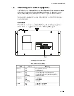
Страница 123: ...n the HUB 100 s AC power source to power it LED display The LEDs on the top of the unit light flash or go off according to equipment status When the equipment is powered all LEDs light then go off LED...

Страница 124: ...orange dashed circle marks the anchor watch range If your ship goes outside the circle ANCHOR WATCH appears in the Alert Box Your ship s position where you start the anchor watch Alarm setting Alarm...

Страница 125: ...menu 2 Select 2 MARK MARK 1 BACK 2 OWN SHIP MARK OFF MIN SCALED 3 STERN MARK OFF ON 4 PI LINE 5 ANCHOR WATCH OFF ON 0 0NM 6 DROP MARK OFF ON 7 INS MARK 1 8 EBL OFFSET BASE STAB GND STAB HDG STAB NORTH...

Страница 126: ...e shown below corresponding DROP MARK box 000 010 020 030 040 050 060 070 080 090 100 110 120 130 140 150 160 170 180 190 200 210 220 230 240 250 260 270 280 290 300 310 320 330 340 350 DROP1 229 8 T...

Страница 127: ...OP 12 ANT4 X BAND AFT OWN RADAR No 2 1 DISP1 ANT1 MASTER 2 DISP2 ANT2 MASTER Not available on IMO or A radar 9 STORE INTER SW NO YES 0 SUB MONITOR OFF ON 3 DISP3 ANT3 MASTER 4 DISP4 ANT4 MASTER 12 3 S...

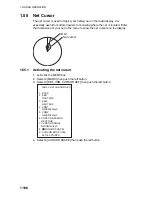
Страница 128: ...et in scale on the display Net cursor EBL2 1 55 1 Activating the net cursor 1 Left click the MENU box 2 Select 2 MARK then push the left button 3 Select 9 EBL VRM CURSOR SET then push the left button...

Страница 129: ...cursor dimensions as follows referring to the illustration at right a Select FRONT HALF LENGTH then push the left button b Spin the scrollwheel to set front half length 0 3000 m then push the left bu...

Страница 130: ...Use the EBL offset feature to anchor the net cursor at net origin point a Push the EBL OFFSET key b Use the trackball to set net origin point c Push the EBL OFFSET key to anchor the net cursor 11 Ste...

Страница 131: ...g range of the radar Rmax varies considerably depending on several factors such as the height of the antenna above the waterline the height of the target above the sea the size shape and material of t...

Страница 132: ...ed by pulselength only Practically a 0 08 microsecond pulse offers the discrimination better than 40 m as do so with all FURUNO radars Test targets for determining the range and bearing resolution are...

Страница 133: ...target as shown below Multiple reflection echoes can be reduced and often removed by decreasing the gain sensitivity or properly adjusting the A C SEA control Own ship Target True echo Multiple echo...

Страница 134: ...he figure below If your ship comes close to a large metal bridge for example such a false echo may temporarily be seen on the screen True echo False echo Own ship Target ship Mirror image of target sh...

Страница 135: ...ange the frequency match during each of the 12 slow sweeps will produce a response on the radar display thus a line of 12 dots equally spaced by about 0 64 nautical miles will be shown When the radar...

Страница 136: ...set up for SART detection do the following 1 Left click the MENU box to open the menu 2 Select 1 ECHO ECHO 1 BACK 2 2 ND ECHO REJ OFF ON 3 TUNE INITIALIZE 4 PM OFF ON 5 SART OFF ON 6 WIPER OFF 1 2 7 E...

Страница 137: ...th Narrow bandwidths of 3 5 MHz are used with long pulses on long range scales and wide bandwidths of 10 25 MHz with short pulses on short ranges A radar bandwidth of less than 5 MHz will attenuate th...

Страница 138: ...r beacon It has a Morse coded pattern Note that the position on the radar display is not accurate RACON RACON 2 5 Radar Target Enhancer RTE An RTE is a radar transponder is mounted on navigation buoys...

Страница 139: ...m sea surface and clutter As the level of clutter changes with environment the operator should properly adjust the A C SEA A C RAIN and GAIN controls to be sure target echoes are not eliminated from t...

Страница 140: ...lays data on tracked target chosen with the trackball TARGET CANCEL Terminates tracking of tracked target chosen with the trackball Control unit RCU 014 Trackball With the cursor inside the effective...

Страница 141: ...dure below 3 4 1 Echo referenced speed input The use of echo referenced speed is recommended when The speed log is not operating properly or not connected to the radar The vessel has no device doppler...

Страница 142: ...tracking speed Do not choose a moving target as a reference target A moving target produces error in the vector for TT and AIS which results in wrong collision avoidance information Further an unstabl...

Страница 143: ...tor appears within one minute to indicate the target s motion trend Within three minutes the initial tracking stage is finished and the target becomes ready for stable tracking At this point the broke...

Страница 144: ...s By keyboard 1 Use the trackball to put the cursor on the tracked target reference target or lost target you wish to cancel tracking 2 Press the TARGET CANCEL key By trackball 1 With the cursor insid...

Страница 145: ...the right side to show the TT TARGET menu TT TARGET menu 2 Select 1 TT SELECT 3 Select MANUAL 100 AUTO 25 AUTO 50 or AUTO 75 as appropriate For details see the table on page 3 5 4 Push the right butt...

Страница 146: ...condition Note 1 For successful acquisition the target to be acquired should be within 0 1 to 24 nm or 32 nm depending on initial setting from own ship and not obscured by sea or rain clutter Note 2...

Страница 147: ...the MENU box to open the menu 2 Select 4 TT AIS to open the TT AIS menu 3 Select 9 TT LOST FILTER 4 Set items 2 and 3 as appropriate referring to the description below MAX RANGE Any TT lost targets be...

Страница 148: ...age Plotting symbol selected for a target acquired manually is shown in bold broken lines Within one minute after acquisition Steady tracking Manual plotting symbol in a bold solid circle within three...

Страница 149: ...ol unit RCU 015 RCU 016 However you can program a function key to do so with the combination of the STD KEY category and the option TARGET DATA 1 Put the cursor on the TT symbol you want to change 2 P...

Страница 150: ...0 ASSOCIATION TT AIS SYMBOL 1 BACK 2 TT AIS SYMBOL COLOR RED GRN BLU YEL CYA MAG WHT 3 AIS ROT TAG LIMIT 0 000 MIN 4 TT PAST POSN POINTS 5 10 5 AIS PAST POSN POINTS 5 10 6 AIS SCALED SYMBOL OFF ON 3...

Страница 151: ...ET DATA ACQ CURSOR MENU in the guidance box 2 Use the trackball to put the cursor on a desired tracked target then push the left button 3 To erase a target s data from the data box select the target o...

Страница 152: ...est Point of Approach of target to own ship TCPA Time to CPA BCR Bow crossing range of target BCT Bow crossing time of target CSE and STW are shown in case of manual speed speed through the water Trac...

Страница 153: ...target list do the following 1 Select the TARGET LIST box at the right side of the screen TARGET LIST TARGET LIST box 2 Push the left button to display the TARGET LIST in the TCPA means that the time...

Страница 154: ...rget vectors can be ground stabilized or sea stabilized You can select ground or sea stabilization from the SPEED menu Select BT Bottom Tracking for ground stabilization or WT Water Tracking for sea s...

Страница 155: ...mode and length Vectors may be displayed in true or relative mode Vector time or the length of vectors can be set between 1 and 60 minutes By keyboard 1 Press the VECTOR MODE key consecutively to sel...

Страница 156: ...past positions of any targets being tracked A new dot is added every minute or at other preset time intervals until the preset number is reached If a target changes its speed the spacing will be unev...

Страница 157: ...INTS 5 10 6 AIS SCALED SYMBOL OFF ON 3 11 2 Past position display attributes You may select the number of past points to display per plotting interval as follows 1 Left click the MENU box to open the...

Страница 158: ...ard the ship for setting information These values are applied to all targets If stationary targets have vectors set and drift values should be adjusted until they lose vectors To enter set and drift d...

Страница 159: ...The reference point for CPA and TCPA calculation may be selected from antenna position or conning position For further details see section 1 50 3 13 1 Setting the CPA and TCPA ranges To set the CPA a...

Страница 160: ...ARGET or AIS NEW TARGET appears in red in the Alert Box The symbol of the offending target is red and flashing Further the AIS display is automatically turned on if it is off 3 14 1 Activating an acqu...

Страница 161: ...sleep state and the guidance box reads AZ WORK L DELETE Note 3 The default acquisition zone is fan shaped It may also be a polygon having 3 10 points For details see section 3 14 5 Note 4 If both acqu...

Страница 162: ...AB NORTH Acquisition zone is fixed to North 5 Push the right button twice to close menu 3 14 5 Acquisition zone shape and stabilization The shape of the No 2 acquisition zone may be a sector or a poly...

Страница 163: ...SION A tracked target is on collision course Take evasive action or terminate tracking of TT TT NEW TARGET Tracked target has entered an acquisition zone The tracked target s symbol is red and flashin...

Страница 164: ...6 1 Types of trial maneuvers There are two types of trial maneuvers static and dynamic Dynamic trial maneuver A dynamic trial maneuver displays predicted positions of the tracked targets and own ship...

Страница 165: ...sition of your ship and tracked targets at the end of the trial maneuver are shown on the display By shortening and extending the trial time you can find the safe time to make a maneuver Thus the stat...

Страница 166: ...SPEED RATE 4 TRIAL TURN RATE Set 1 0kt 0 00kn s 0kt 0 00kn s Set 2 Set 1 0kt 0 0 s 0kt 0 0 s Set 2 Set speed and turn rate to zero 0 to simulate course and speed changes not affected by ship s inerti...

Страница 167: ...moved from the box the original positions of your ship and tracked targets are restored If a manuever is unsafe change speed course and delay until it is safe The trial maneuver takes place with the l...

Страница 168: ...2 START NO SELECT 1 BACK 3 17 TT Performance Test A test program is provided for assessing overall performance of the TT Normal operation is suspended and the indication S appears at the bottom of th...

Страница 169: ...rs at the right side of the display 8 Confirm that test data displayed for target A matches the data shown in the table below Range bearing and TCPA change over time 9 Confirm that data for target B a...

Страница 170: ...king is achieved when the target is clearly distinguishable on the display for 5 out of 10 consecutive scans whether acquired automatically or manually Required tracking facilities are available withi...

Страница 171: ...speed of own ship are computed from own ship s gyro and speed inputs and the resulting course and speed of each tracked target is easily computed by vector summing of the relative motion with own ship...

Страница 172: ...visible if the radar sensitivity control GAIN control were increased The setting of the correct radar receiver gain is not critical but the target should be on the radar PPI and be clearly visible and...

Страница 173: ...n certain cases false echoes in the shadow sector cause the TT system to acquire track and vector them Shadow sectors should be avoided Indirect echoes A target at close range is usually picked up dir...

Страница 174: ...3 TARGET TRACKING TT 3 36 This page is intentionally left blank...

Страница 175: ...ion You may disable or enable the AIS display from the AIS DISP box 4 1 Controls for AIS Keyboard The AIS uses the keys shown below ACQ ON MENU OFF VRM A C SEA A C RAIN MODE 3 LINE INDEX 6 OFF 2 1 HL...

Страница 176: ...with thick line Color is selectable from menu Displayed for turning ship Displayed when CPA TCPA is within CPA TCPA LIMIT Red in color Flashing until acknowledged A X overlaid on a lost target Red in...

Страница 177: ...AIS appears in red in the Alert Box No water or ground tracking speed received from AIS target or no speed data from AIS target The symbol of the corresponding AIS target is shown in dotted lines Note...

Страница 178: ...not require close monitoring 1 Left click the MENU box to open the menu 2 Select 4 TT AIS to open the TT AIS menu TT AIS menu 3 Select 7 AIS DISP FILTER AIS DISP FILTER menu 4 Set items 2 5 referring...

Страница 179: ...activate that is know more about a vessel s motion 3 Push the left button to activate the target Heading line 2 SOG Speed over Ground and COG Course over Ground vector 1 Turning direction ROT 1 Vector...

Страница 180: ...CEL EXIT in the guidance box 2 Use the trackball to put the cursor on an activated AIS target symbol 3 Push the left button The activated target symbol is replaced with the sleeping target symbol Slee...

Страница 181: ...o enter at the start of a voyage navigational status ETA destination draught and crew 1 Right click the AIS DISP box at the right side of the screen to open the AIS TARGET menu AIS TARGET MENU 1 SLEEP...

Страница 182: ...ed for future use 14 AIS SART No use 15 Not defined 5 Select 3 ETA then push the left button 6 Use the scrollwheel to enter estimated date and time of arrival in order of day two digits month year fou...

Страница 183: ...nd AIS data is shown in the AIS data box when the target is correctly selected A Location of target s data box Not shown on W type radar Activated target selected for data display AIS B MMSI 665498114...

Страница 184: ...ESTINATION KOBE ETA 01 FEB 12 59 AIS VERSION 0 ASSOCIATION OFF SHIP CARGO TYPE CARGO SHIPS ALL SHIPS OF THIS TYPE Ship s name Call sign Latitude Longitude Position fixing device Position accuracy HIGH...

Страница 185: ...e 2 3 Select 7 AIS SYMBOL 4 Roll the scrollwheel to adjust brilliance 5 Push the right button twice to close the menu 4 8 2 AIS symbol size and color You may select the size and color of the AIS symbo...

Страница 186: ...be uneven If it changes course its plotted course will not be a straight line Note that AIS past positions will be shown if TARGET TRACK on the DISPLAY sub menu of the PLOTTER menu is ON regardless o...

Страница 187: ...ailable on IMO type AIS SYMBOL menu 4 Select 5 AIS PAST POSN POINTS 5 Select 5 or 10 as appropriate 6 Push the right button three times to close the menu 4 9 3 Past position display motion The past po...

Страница 188: ...is displayed when the ALARM ACK key is pressed or the ALARM ACK box is clicked to acknowledge an AIS lost target the TT lost target also is erased Note 2 The AIS data transmission interval depends on...

Страница 189: ...GTH Any AIS lost targets whose length is shorter than this setting will not trigger the lost target alarm 5 Push the right button several times to close the menu 4 10 2 Enabling disabling the lost tar...

Страница 190: ...n the TT AIS menu TT AIS SYMBOL 1 BACK 2 TT AIS SYMBOL COLOR RED GRN BLU YEL CYA MAG WHT 3 AIS ROT TAG LIMIT 000 0 MIN 4 TT PAST POSN POINTS 5 10 5 AIS PAST POSN POINTS 5 10 6 AIS SCALED SYMBOL OFF ON...

Страница 191: ...ollowing 1 Left click CPA LIMIT box to show the CPA and TCPA boxes Not necessary if the CPA and TCPA boxes are already shown CPA LIMIT 0 5NM 10MIN TCPA Box CPA LIMIT Box CPA Box CPA LIMIT CPA and TCPA...

Страница 192: ...h 1 Left click the MENU box to open the menu 2 Choose 4 TT AIS 3 Choose 6 CPA AUTO ACTIVATE CPA AUTO ACTIVATE menu 4 Set items 2 5 as appropriate MAX RANGE Any AIS target beyond this range will not be...

Страница 193: ...selected and displayed If the AIS and radar information become sufficiently different the AIS and radar information shall be considered as two distinct targets One activated AIS target and one tracke...

Страница 194: ...get and tracked target setting range 0 000 0 999 nm RANGE Enter the range direction difference from own ship to AIS target and tracked target setting range 0 000 0 999 nm BEARING Enter the bearing dif...

Страница 195: ...be viewed as follows 1 Right click the AIS DISP box at the right side of the screen to open the AIS TARGET menu 2 Select 7 STATIC DATA 1 BACK TYPE OF SHIP 000 ALL SHIPS OF THIS TYPE CALL SIGN call sig...

Страница 196: ...you how to create and save a message Nine messages may be saved Note You can display the TRANSMIT MESSAGE menu and set ship s MMSI no by right clicking the appropriate AIS target in the AIS target dat...

Страница 197: ...OADCAST SAFETY 161 12 Select END then push the left button 13 Select 7 SAVE FILE 14 Select appropriate number 15 Push the right button to close the menu 4 15 2 Transmitting messages 1 Right click the...

Страница 198: ...st AIS message is automatically erased to make room for the latest Note that received messages and alarm messages are not backed up when the power is turned off Manually viewing received messages To v...

Страница 199: ...Right click the AIS DISP box 2 Select 3 AUTO DISP MESSAGES 3 Select ON 4 Push the right button to close the menu When a message arrives the message arrival icon appears at the right hand side of the...

Страница 200: ...orting intervals whichever is the shorter AIS TARGET 95 Appears when capacity for AIS targets is 95 full AIS TARGET FULL The radar only displays the closest 1000 AIS targets from own ship ASSOCIATION...

Страница 201: ...nts are available Own ship and other ship tracks may be stored at a selected interval Charts A B C and W types are superimposed on the radar picture without disturbing the radar observation The chart...

Страница 202: ...Head up Head up TB True Bearing Stern up and North up TM True Motion To select a mode use the MODE key or select the PRESENTATION MODE box then push the left button For a description of the presentat...

Страница 203: ...rom the actual own ship location The radar map does not affect any radar function 5 4 1 Showing hiding the radar map display From menu 1 Use the trackball to select the MARK box 2 Push the right butto...

Страница 204: ...COLOR pushing the scrollwheel then choosing color desired Note 2 On the W type the indication MAP appears to the right of the MARK box 5 Push the right button to close the menu The guidance box now r...

Страница 205: ...y Green Buoy Buoy Red Buoy Danger Highlight Green Buoy Mark Purple Danger Highlight Mark Purple Danger Highlight Mark Orange Mark Mark Orange Mark Mark Orange Mark Mark Purple Navline map Mark White C...

Страница 206: ...ance box 2 Use the trackball to put the cursor on the radar map mark or line you wish to erase 3 Push the left button to erase selected mark or line Note When erasing a line the cursor location determ...

Страница 207: ...R menu 3 Select 8 DATA ERASE 1 Colors not shown on IMO type 2 Not available on IMO type 3 Not available on IMO or A type DATA ERASE 1 BACK 2 OWN TRACK 1 RED GRN BLU YEL CYA MAG WHT 30 50 80 ALL 3 TARG...

Страница 208: ...radar map correction display CHART ALIGN L OFF EXIT in the guidance box then push the left button until MAN ALIGNED disappears from the screen 5 6 2 Cursor data correction You can correct cursor data...

Страница 209: ...active gases Keep cards away from water and chemicals Keep the connector free foreign material Do not drop the cards Chart cards are intended as an aid to navigation The navigator has the responsibil...

Страница 210: ...een To release the chart position correction display CHART ALIGN L OFF EXIT in the guidance box then push the left button until CHART ALIGN disappears from the screen 5 7 3 Correcting cursor data 1 Le...

Страница 211: ...COLOR GRN YEL CYA ORANGE GRAY 3 OWN TRACK INTERVAL OFF DRAW 10S 30S 1M 2M 3M 6M 15M 4 OWN TRACK COLOR RED GRN BLU YEL CYA MAG WHT 5 TGT TRACK INTERVAL OFF DRAW 10S 30S 1M 2M 3M 6M 15M 6 TGT TRACK COLO...

Страница 212: ...OWN TRACK OFF ON 4 TARGET TRACK OFF ON 5 MARK OFF ON 6 LAND DENSITY OFF ON 7 PLACE NAME OFF ON 8 COAST LINE OFF ON 9 CONTOUR LINE OFF ON DEPTH 0 NEXT DISPLAY 2 2 1 BACK 2 NAV LINE MAP OFF ON 3 DANGER...

Страница 213: ...3 min 41 days 16 hr 1 min 13 days 21 hr 20 min 6 min 83 days 8 hr 1 Left click the MENU box to open the menu 2 Select 5 PLOTTER to open the PLOTTER menu PLOTTER 1 BACK 2 CHART COLOR GRN YEL CYA ORANG...

Страница 214: ...ve the memory The table below shows the relation between plotting interval and maximum track recording time for other ships track Other target plot interval and storage time Interval Max Recording Tim...

Страница 215: ...menu If you selected OFF at step 4 go to step 6 to assign a number to a track 6 Put the cursor inside the effective display then spin the scrollwheel to show TARGET TRACK ON EXIT in the guidance area...

Страница 216: ...own on IMO type 2 Not available on IMO type 3 Not available on IMO or A type DATA ERASE 1 BACK 2 OWN TRACK 1 RED GRN BLU YEL CYA MAG WHT 30 50 80 ALL 3 TARGET TRACK 2 RED GRN BLU YEL CYA MAG WHT 30 50...

Страница 217: ...similarly 7 Push the right button three times to close the menu Erasing track between two points area 1 Place the cursor inside the effective display area 2 Spin the scrollwheel to show OWN TRACK DELE...

Страница 218: ...lected mark number 162 5 T 11 7NM Bearing and range from own ship to waypoint 1 MARK box 2 Push the right button to open the MARK menu MARK MENU 1 ORIGIN MARK STAB GND SEA 2 MARK KIND ORIGIN MARK No O...

Страница 219: ...trackball to put the cursor where you want to inscribe a waypoint mark then push the left button to inscribe the mark The waypoint mark waypoint number appears at the location selected You can see the...

Страница 220: ...ordinate polarity roll the scrollwheel or use the 2 key in case of keyboard operation 9 To enter another waypoint repeat steps 4 8 10 Push the right button three times to close the menu 5 10 2 Editing...

Страница 221: ...er waypoint repeat steps 2 and 3 5 To finish push the right button when the guidance reads MARK DELETE EXIT Erasing all waypoints 1 Left click the MENU box to open the menu 2 Select 5 PLOTTER to open...

Страница 222: ...data of all registered waypoints Each page of the waypoint list holds eight waypoints To display the waypoint list 1 Right click the MENU box at the right side of the screen to open the menu 2 Select...

Страница 223: ...ing waypoint name and number You may turn waypoint name and number display on or off as desired 1 Left click the MENU box to open the menu 2 Select 8 NAV LINE WPT 3 Select 0 NEXT NAV LINE WPT menu 2 2...

Страница 224: ...e MENU box to open the menu 2 Select 8 NAV LINE WPT 3 Select 8 NAV LINE SET NAV LINE SET menu 4 Select 2 NAV LINE NO SELECT 5 Use the scrollwheel to enter nav line no in two digits 6 Select 3 NAV LINE...

Страница 225: ...SELECT 5 Use the scrollwheel to enter nav line number to edit 6 To edit nav line name Select 3 NAV LINE NAME Use the scrollwheel to change name 7 To replace waypoints in a nav line do the following 1...

Страница 226: ...nav line list which shows all nav lines registered may be displayed as follows 1 Left click the MENU box to open the menu 2 Select 8 NAV LINE WPT 3 Select 9 NAV LINE LIST NAV LINE LIST 4 To go to a n...

Страница 227: ...below A nav line that is currently in use cannot be erased Erasing individual nav lines 1 Left click the MENU box to open the menu 2 Select 8 NAV LINE WPT 3 Select 8 NAV LINE SET NAV LINE SET menu 4...

Страница 228: ...CK 2 RED GRN BLU YEL CYA MAG WHT 30 50 80 ALL 4 MARK ALL ERASE NO YES 5 WPT ALL ERASE NO YES 6 NAV LINE ALL ERASE NO YES 7 OWN TRACK DELETE 3 2POINTS AREA 8 TARGET TRACK DELETE 3 2POINTS AREA DATA ERA...

Страница 229: ...this setting when the vessel is not to correct cross track error to return to course set after arriving at turning line location REVISED Use this setting when vessel is to return to course set after...

Страница 230: ...elect appropriate option then push the scrollwheel 8 To skip the next waypoint Select 2 SKIP NEXT WPT 9 Push the right button twice to close the menu Displaying external nav lines Nav lines from an ex...

Страница 231: ...the radar display by following the procedure shown below 000 010 020 030 040 050 060 070 080 090 100 110 120 130 140 150 160 170 180 190 200 210 220 230 240 250 260 270 280 290 300 310 320 330 340 35...

Страница 232: ...se with the system and deletes all data recorded in the memory card You can format cards you ve used before however in which case all prior information on them is erased 1 Insert a blank memory card i...

Страница 233: ...ears 5 12 2 Recording data When the memory becomes full the oldest track is erased to make room for the latest Further when the memory is full you cannot enter another mark or line unless you erase un...

Страница 234: ...d as follows M Radar map mark 20 000 points W Waypoint nav line Waypoint 20 points nav line 30 lines T Own track 20 000 points A Target track 1 000 points x 15 targets S Setting data all operating inf...

Страница 235: ...MENU box to open the menu 3 Select 6 CARD CARD menu 4 Select 2 DRIVE SELECT 5 Select the drive where you inserted the memory card 6 Push the left button 7 Select 3 READ CARD and push the scrollwheel...

Страница 236: ...oints Own ship s track 20 000 points Other ships tracks 1 000 points x 15 targets 5 14 Deleting Files 1 Left click the MENU box to open the menu 2 Select 6 CARD 3 Select 2 DRIVE SELECT 4 Select the ap...

Страница 237: ...rk inside the equipment Turn off the radar power switch before servicing the antenna unit Post a warn ing sign near the switch indicating it should not be turned on while the antenna unit is being ser...

Страница 238: ...ssary clean and repaint them thickly Replace them if heavily corroded Sealing compound may be used instead of paint Apply a small amount of grease between nuts and bolts for easy removal in future Ant...

Страница 239: ...worn Magnetron MAF 1425B X band 12 kW MG4010 X band 12 kW MG5436 X band 25 kW MG5223F S band 30 kW 4 000 h 4 000 h 4 000 h 7 000 h Check no of hours used at Tx time Reset time after replacement Backli...

Страница 240: ...ssor Unit 220 230 VAC 5A 100 230 VAC 2A Display Unit MU 201CR 24 VDC 5A 100 230 VAC 2A Display Unit MU 231CR 24 VDC 6A 12 VDC 10A Display Unit MU 170C 24 VDC 5A Display Unit MU 231 100 230 VAC 1 5A Di...

Страница 241: ...ring and ball 3 Clean the ball with a soft lint free cloth then blow carefully into the ball cage to dislodge dust and lint 4 Look for a build up of dirt on the metal rollers If dirty clean the roller...

Страница 242: ...power to restore normal operation Range changed but radar picture does not change Defective range key or video freeze up Try to hit RANGE and keys or RANGE box several times If unsuccessful replacemen...

Страница 243: ...perate at all 1 Blown fuse 2 Mains voltage polarity 3 Power supply board 1 Replace blown fuse 2 Correct wiring and input voltage 3 Replace power supply board Brilliance adjusted but no picture SPU boa...

Страница 244: ...pulse is not received during transmitting 2 Replace the gyro interface Cannot operate radar from on screen boxes SPU Board Replace SPU Board Radar is properly tuned but poor sensitivity 1 Deteriorated...

Страница 245: ...ot functioning properly Improper setting of A C SEA If A C SEA is seen only at very close range suspect inaccurate frequency of reference oscillator True motion presentation not working correctly 1 Po...

Страница 246: ...en the menu 2 Select 9 CUSTOMIZE TEST CUSTOMIZE TEST menu 3 Select 8 TEST TEST menu 4 Select 2 SELF TEST SELF TEST menu 5 Select 2 START to start the test In a few moments the results of the test are...

Страница 247: ...1 6 MAG CURRENT 1 5 HEATER 1 8 12V 11 9 12V 11 8 5V 4 8 32V 31 8 TUNE OUT 19 2 TRIGGER FREQ 2273 ANT SPEED 21 6 Program Version No Installed card units are shown 0 0 0 0 0 0 0 0 0 0 0 0 Self test res...

Страница 248: ...being input from external equipment GPS1 GPS2SPEED HEADING and NAV DATA Below is an example The sentences shown depend on your system settings GPS1 GGA GLL RMC RMB VTG ZDA DTM BWR BWC GPS2 GGA GLL RM...

Страница 249: ...SHOOTING 6 13 8 Press the F1 key again to show the data sentences input from AIS and INS AIS VDO VDM INS ZDA GGA GLL OSD DPT MWV DTM FUGLL PAESP PAESC PAESF PLSPL PLSPS PAESW PAESN 8 To terminate the...

Страница 250: ...6 MAINTENANCE TROUBLESHOOTING 6 14 This page intentionally left blank...

Страница 251: ...4 4 WATCH ALARM OFF 6M 10M 12M 15M 20M 5 ALARM SOUND LEVEL OFF LOW MID HIGH 6 ALARM OUT1 7 ALARM OUT2 8 ALARM OUT3 9 ALARM OUT4 0 PRIMARY ALARM 1 Not available on IMO or A type 2 W type shows PI LINE1...

Страница 252: ...N TRACK COLOR RED GRN BLU YEL CYA MAG WHT 5 TGT TRACK INTERVAL OFF DRAW 10S 30S 1M 2M 3M 6M 15M 6 TGT TRACK COLOR RED GRN BLU YEL CYA MAG WHT 7 CURSOR L L ALIGN OFF ON 8 DATA ERASE 1 BACK 2 OWN TRACK...

Страница 253: ...RK 5 WR NAV LINE WPT 6 WR OWN TRACK 7 WR TARGET TRACK 8 WR SETTING DATA 9 WR INSTALL DATA 0 NEXT 1 BACK 2 FILE DELETE 3 CARD INITIALIZE 1 BACK 2 DEPTH OFF m ft 3 DEPTH GRAPH SCALE 10 20 50 100 200 500...

Страница 254: ...A C SEA SELECT AUTO RAIN SELECT TUNE SELECT ANT HEIGHT SEA CONDITION 2ND ECHO REJ PM SART WIPER 1 BACK 2 ALARM ACK STBY TX HL OFF EBL OFFSET MODE OFF CENTER CU TM RESET PI LINE VECTOR TIME VECTOR MODE...

Страница 255: ...POPUP GUIDANCE OFF ON 1 6 OWN SHIP VECTOR OFF HDG COURSE 7 STERN UP OFF ON 8 SHUTTLE FERRY OFF MODE1 MODE2 0 NEXT 1 BACK 2 SELF TEST 3 TT TEST 6 PICTURE 1 BACK 2 PICTURE1 PICTURE 2 PICTURE 3 PICTURE...

Страница 256: ...TRAIL 3 4 OFF 1 2 1 Shown when 12H 24H or 48H is chosen at 8 TRAIL LENGTH 2 B and W types 48H not available on W type 3 Not available on IMO type 4 Not available on A type 8 TRAIL LENGTH 2 NORMAL 12...

Страница 257: ...4 NOISE REJ OFF ON 5 AUTO STC OFF ON 6 AUTO RAIN 7 VIDEO CONTRAST 1 2 3 4 A B C 8 PULSE 9 CONDITION PICTURE menu OFF 1 2 3 4 PULSE menu ANTENNA SELECT menu ANT SELECT ANT NO 1 X BAND 12 MAIN TOP ANT...

Страница 258: ...D2 D3 D4 D5 D6 D7 Start bit Stop bit Data bits Validity and integrity of input data mode indicator Data indication HDG Latitude and Longitude SPD COG SOG WP GREEN color normal data THS A HDT GNS A D...

Страница 259: ...R LF 2 1 1 Local alarm number identifier 2 Checksum BWC Bearing and distance to waypoint Not available on IMO radar BWC hhmmss ss llll ll a yyyyy yy a x x T x x M x x N c c a hh CR LF Checksum Mode in...

Страница 260: ...C of observation 2 Waypoint latitude N S 3 Waypoint longitude E W 4 Bearing degrees true 5 Bearing degrees magnetic 6 Distance nautical miles 7 Waypoint ID 8 Mode indicator see note 9 Checksum NOTE Po...

Страница 261: ...code 3 Lat offset min N S 4 Lon offset min E W 5 Altitude offset m 6 Reference datum W84 WGS84 W72 WGS72 S85 SGS85 P90 PE90 7 Checksum DBS Depth below surface DBS x x f x x M x x F hh CR LF 4 3 2 1 1...

Страница 262: ...quality indicator see note 5 Number of satellite in use 00 12 may be different from the number in view 6 Horizontal dilution of precision 7 Antenna altitude above below mean sea level m 8 Geoidal sepa...

Страница 263: ...be set to V invalid for all values of Operating Mode except for A Autonomous and D Differential The positioning system Mode indicator and Status field shall not be null fields Position data shown in g...

Страница 264: ...2 1 1 Temperature degrees C 2 Checksum MWV Wind speed and angle MWV x x a x x a A hh CR LF 6 5 4 3 2 1 1 Wind angle 0 to 359 degrees 2 Reference R relative T true 3 Wind speed 4 Wind speed units KN M...

Страница 265: ...Arrival status A arrival circle entered or perpendicular passed 12 Mode indicator see note 3 13 Checksum NOTES 1 If range to destination exceeds 999 9 nautical miles display 999 9 2 If cross track err...

Страница 266: ...iation degrees E W 9 Mode indicator see note 10 Checksum NOTE Positioning system Mode indicator A Autonomous D Differential E Estimated dead reckoning M Manual input S Simulator N Data not valid The M...

Страница 267: ...e all waypoints w working route first listed waypoint is FROM second is TO and remaining reset of route 4 Route identifier 5 Waypoint identifier 6 Waypoint n identifier 7 Checksum THS True heading and...

Страница 268: ...Stern transverse water speed knots 8 Status stern water speed A data valid V data invalid 9 Stern transverse ground speed knots 10 Status stern ground speed A data valid V data invalid 11 Checksum Da...

Страница 269: ...to 12 UTC 8 Navigational status 0 to 15 9 Regional application flags 0 to 15 10 Checksum VTG Course over ground and ground speed VTG x x T x x M x x N x x K a hh CR LF 6 5 4 3 2 1 1 Course over ground...

Страница 270: ...econd 4 Wind speed Km Hr 5 Checksum VWT True wind speed and angle VWT x x a x x N x x M x x K hh CR LF 5 4 3 2 1 1 Calculated wind angle relative to the vessel 0 to 180 left right L R of vessel headin...

Страница 271: ...Local alarm number identifier 3 Alarm condition A threshold exceeded V not exceeded 4 Alarm s acknowledge state A acknowledged V unacknowledged 5 Alarm s description text 6 Checksum AIVDM VHF data li...

Страница 272: ...ETA destination draught type of ship call sign ship s name and GPS antenna position Output sentences ABM UAIS Addressed binary and safety related message ABM x x x xxxxxxxxx x xx s s x hh CR LF 9 8 7...

Страница 273: ...nowledged V unacknowledged 5 Alarm s description text 6 Checksum BBM UAIS Broadcast binary message BBM x x x x xx s s x hh CR LF 8 7 6 5 4 3 2 1 1 Total number of sentences needed to transfer the mess...

Страница 274: ...ourse reference B M W R P see note 5 Vessel speed 6 Speed reference B M W R P see note 7 Vessel set degrees true Manually entered 8 Vessel drift speed Manually entered 9 Speed units K km h N Knots S s...

Страница 275: ...7 VRM2 range 8 EBL2 degrees 9 Cursor range from own ship 10 Cursor bearing degrees clockwise from 0 11 Range scale in use 12 Range units K N S 13 Display rotation see note 1 14 Checksum NOTES 1 Displa...

Страница 276: ...de For non IMO specification radar This function outputs event mark position TLL xx llll lll a yyyyy yyy a c c hhmmss ss a a hh CR LF 8 7 6 5 4 3 2 1 1 Target number 00 99 2 Latitude N S 3 Longitude E...

Страница 277: ...11 10 9 8 7 6 5 4 3 2 1 1 Target number 00 to 99 2 Target distance from own ship 3 Bearing from own ship degrees true relative T R 4 Target speed 5 Target course degrees true relative T R 6 Distance...

Страница 278: ...igh A B 0 2V Logical Low A B 0 2V RD A RD B GND Log navigator Baud rate is adaptive with RX data Complies with IEC 61162 1 PC 400 Photo Coupler RD A RD B 470 ohm This port is an opticoupler used to is...

Страница 279: ...and receivers TD A TD B Logical High A B 0 2V Logical Low A B 0 2V Serial interface input output ports Baud rate is fixed at 38 4 kbps Complies with IEC 61162 2 AIS Input port RD A B LTC1535 Isolated...

Страница 280: ...26N CONTROL UNIT RCU 015 PNL Board 03P9344 Trackball Assy TA4726N MONITOR UNIT MU 201CR PWR Pack RKW 12 13RE AC spec DC DC Board 03P9359 DC spec Noise Filter CF 205A AC spec MXB 1206 33 DC spec DVI I...

Страница 281: ...09P0612H755 26S0063 FAN2 FAN3 MFB52A 12HA 001 26S0028 FAN1 LCD Code No LQ231U1LW32 26S0062 FAN Code No 26P0013 Monitor unit MU 190 ELECTRICAL PARTS Model FAR 2107 D Unit Monitor Unit MU 190 OZP 120 12...

Страница 282: ...ER CHASSIS RSB 096 24 rpm RSB 097 42 rpm RF MODULE RTR 078 FAR 2117 BB D 2817 D RTR 079 FAR 2127 BB D 2827 D MIC ASSEMBLY RU 9601 FAR 2117 BB D 2817 D RU 9603 FAR 2127 BB D 2827 D MOTOR D8G 516 24 rpm...

Страница 283: ...347 MOTOR D8G 516 2010 11 Transceiver unit RTR 081 for FAR 2827W D FURUNO Model FAR 2827W D Unit Transceiver Unit RTR 081 ELECTRICAL PARTS LIST SYMBOL NAME REMARKS PRINTED CIRCUIT BOARD TB 03P9349 IF...

Страница 284: ...ER CHASSIS RSB 098 21 26 rpm RSB 099 21 26 rpm RSB 100 45 rpm RSB 101 45 rpm RSB 102 45 rpm RF MODULE RTR 080 MIC ASSEMBLY RU 9760A MOTOR RM 7398 RSB 098 099 21 26 rpm 200 220V 3 RM 7435 RSB 098 099 2...

Страница 285: ...LAY 2010 11 Antenna unit RSB 104 105 for FAR 2837SW D FURUNO Model FAR 2837SW D Unit Antenna Unit RSB 104 105 ELECTRICAL PARTS LIST SYMBOL NAME REMARKS PRINTED CIRCUIT BOARD TB 03P9349 BP GEN 03P9347...

Страница 286: ...ansceiver Unit RTR 082 ELECTRICAL PARTS LIST SYMBOL NAME REMARKS PRINTED CIRCUIT BOARD TB 03P9349 IF AMP 03P9335 PWR 03P9348 MD 03P9244 RFC 03P9346 MIC ASSEMBLY RU 9760A MOTOR TR LIMITER TL378A CIRCUL...

Страница 287: ...SM 501A Monitor unit MU 231CR rear cover removed Inverter Board NA19002 4241 LCD Unit FLC59YXC8V 04 LCD Board NA21808 Monitor unit MU 231CR inner shield plate removed Monitor unit MU 231 AC specificat...

Страница 288: ...onitor unit MU 201CR rear cover removed Inverter Board 210PW021 C LCD Board 201PW023 H LCD Unit NL128102AC31 02 Monitor unit MU 201CR inner shield plate removed Monitor unit MU 190 MFB52A 12HA 001 26S...

Страница 289: ...trol unit RCU 014 BUZ Board 03P9362 Trackball Assy TA4726N PNL Board 03P9343 Control unit RCU 014 rear cover removed Control unit RCU 015 Trackball Assy TA4726N PNL Board 03P9344 Control unit RCU 015...

Страница 290: ...46 RF PWR Board 03P9348 Circulator RC 3686 Diode Limiter RU 9099 IF Board 03P9355 MIC Assy RU 9601 FAR 2117 BB D 2817 BB D RU 9603 FAR 2127 BB D 2827 D Transceiver unit RTR 078 079 upper half MD Board...

Страница 291: ...AP 41 MD Board 03P9244 B Magnetron MG5436 Pulse Transformer RT 9203 Transceiver unit RTR 079 lower half Antenna unit RSB 103 for FAR 2827W D BP Board 03P9347 RF Board 03P9349 Motor DG8 516 Antenna uni...

Страница 292: ...WR Board 03P9348 IF Amplifier 03P9335 MIC Assy RU 9601 Diode Limiter RU 9099 Circulator RC 3686 RFC Board 03P9346 Underneath MD Board 03P9244 Pulse Converter RT 9023 Magnetron MG5436 Circulator RC 368...

Страница 293: ...3 RM 7435 RSB 099 21 26 rpm 380 440V 3 RM 9519 RSB 100 45 rpm 220V 3 50 Hz RM 9520 RSB 101 45 rpm 220V 3 60 Hz RM 9521 RSB 102 45 rpm 440V 3 60 Hz MIC Assy RU 9760A Behind plate Diode Limiter RU 9426...

Страница 294: ...APPENDIX AP 44 RFC Board 03P9346 Magnetron MG5223F MD Board 03P9244 Pulse Transformer RT 9773 Antenna unit RSB 098 099 100 101 102 cover opened...

Страница 295: ...m 200 V 3 50 Hz For RSB 104 26 rpm 220 V 3 60 Hz RM 7345 For RSB 105 21 rpm 380 V 3 50 Hz For RSB 105 26 rpm 440 V 3 60 Hz TB Board 03P9349 Antenna unit RSB 104 105 cover opened MSS Board MSS 7497 200...

Страница 296: ...quivalent to 1 minute at 0 degree latitude 2 minutes at 60 degrees latitude 3 minutes at 70 degrees latitude and so on For this reason a longitude error occurs on the radar display For example when ow...

Страница 297: ...694117 0 81103484 0 3061092 0 43117887 0 21881975 0 1 20131324 1 14577786 1 05546143 0 93315023 0 78260251 0 60843159 0 41596331 0 21107193 0 1 14905813 1 09582188 1 00932899 0 89225746 0 74821409 0 5...

Страница 298: ...sitions PAST POSN Delay DELAY Performance Monitor MON DEL Performance Monitor PM DELETE Port Portside PORT Depth DEPTH Position POSN Depth DPTH Power PWR Destination DESTINATION Predicted PRED Differe...

Страница 299: ...egrated Navigation System INS Time to CPA TCPA Interference Rejection INT REJECT Time To Go TTG Interference Rejection IR Track TRK Interval INT Tracking TRKG Interval INTERVAL Trail s TRAIL January J...

Страница 300: ...t VRM1 VRM2 Electronic Bearing Lines from left EBL1 EBL2 OS mark Cursor Heading line North marker Stern marker Barge icon Drop mark Radar map symbols for B C and W type radars Mark Danger Highlight Bu...

Страница 301: ...ight Orange Mark Orange Mark TT symbols Acquired targets from left initial acquisition one minute after acquisition steady tracking lost target target selected for data readout TT symbols user may cha...

Страница 302: ...APPENDIX AP 52 This page intentionally left blank...

Страница 303: ...rpm 60 Hz 45 rpm HSC high speed craft FAR 2827W 24 rpm FAR 2837SW 21 rpm 50 Hz 26 rpm 60 Hz 1 5 Wind tolerance Relative wind 100 kn 1 6 De icer option On When temperature goes down to 5 C Off When te...

Страница 304: ...4 6 6 6 6 3 6 Range accuracy 1 of the maximum range of the scale in use or 10m whichever is the greater 3 7 Bearing discrimination 0 98 XN5A 2 1 XN12AF 1 5 XN20AF 1 2 XN24AF 2 0 SN36AF 3 8 Bearing ac...

Страница 305: ...50 Hz 220 VAC 3 60 Hz 380 VAC 3 50 Hz 440 VAC 3 60 Hz 220 VAC 3 50 Hz HSC 220 VAC 3 60 Hz HSC 440 VAC 3 60 Hz HSC FAR 2137S 2837S 3 0 A 1 5 A 3 5 A 3 5 A 1 7 A FAR 2837SW 3 0 A 1 5 A 5 4 Console 115 2...

Страница 306: ...00 9 1 Access format CSMA CD 9 2 Switching format Store and Forward 9 3 Transmission speed Semi duplex 10 Mbps 100 Mbps Full duplex 20 Mbps 200 Mbps 9 4 Cable category 10 BASE T Category 3 or higher S...

Страница 307: ...g manually 4 24 past position display plotting interval 4 12 past position points 4 13 ROT setting 4 16 sleeping a target 4 6 symbol brilliance 4 11 symbol color 4 11 symbol size 4 11 system messages...

Страница 308: ...eadout 1 16 H HDG box 1 16 HDG menu 1 16 Heading line 1 59 Head up mode 1 18 Head up true bearing mode 1 19 HL OFF box 1 59 HL OFF key 1 59 I INDEX LINE key 1 52 INS marker 1 61 Interference rejector...

Страница 309: ...ports 28 output ports 29 Set and drift 3 20 SET box 3 20 Shuttle ferry 1 82 SOG 1 22 3 20 SPD box 1 22 Speed automatic input 1 22 echo referenced input 3 3 manual input 1 23 SPEED menu 1 22 STBY TX ke...

Страница 310: ...TUNE box 1 15 Tuning automatic or manual 1 16 initializing 1 15 TX STBY box 1 1 V Video plotter auto target track 5 15 chart display 5 9 chart land color 5 11 chart position correction 5 10 cursor da...

Страница 311: ...e B No 165 120 EC0735 Unique ID 4340784 165 111 EC0735 Unique ID 4340784 of 23 September 2008 issued by Federal Maritime and Hydrographic Agency BSH The Federal Republic of Germany EC Quality System M...

Страница 312: ...42 rpm RSB 098 x x 21 26 rpm RSB 099 x x 21 26 rpm Turning unit RSB 100 x x 45 rpm RSB 101 x x 45 rpm RSB 102 x x 45 rpm RSB 103 x x 24 rpm RSB 104 x 21 26 rpm RSB 105 x 21 26 rpm MU 201CR x x x x x...

Отзывы: