


BX-7300 • 180403
© www.funkamateur.de
7
Mounting
Automatic Antenna Selector
proximate 0.5mm spacing off the board so as to avoid an
eventual accidental short circuit caused by solder flows to-
wards the Quartz casing.
A short piece of wire is soldered adjacent to the casing. It is
to be noted that the Quartz housing is to be only briefly
heated and very quickly soldered with the 400 deg C. solder-
ing iron and only for as long as the solder flows. (If you're
not confident soldering this particular case then the piece of
wire can be left out as it only serves to additionally reduce
any spurious emission of the already well constrained
Quartz oscillator and has no special other function.
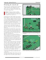
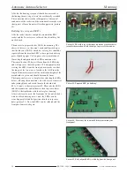
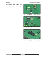
Pictures 3 to 7 show various stages of construction and can
be used to show orientation. For the first IC, mount the 5 V
voltage regulator IC3. This is shown mounted in picture 8.
First the three connectors must be bent with the aid of some
tweezers at about 4mm from the housing. These will be
fixed into the holes before laying the chip flat in the correct
position on the board. Under light pressure (to transfer heat
to the wider casing) warm the top end of the flat cooling
vane of IC3 with the help of a 100W soldering iron and
at the same time tip some solder into the inside of the
3.6mm hole in the cooling vane. After a short time the cas-
ing will be hot enough so that any solder remaining in the
crack under the IC runs away.
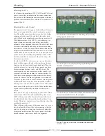
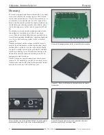
Picture 6. Mounted push buttons
Picture 7. Earthing wire on Quartz housing.
Picture 8. Soldered 5 V voltage regulator
Содержание BX-7300
Страница 20: ...BX 7300 February 2018...


