Funk Amateur BX-7300 Скачать руководство пользователя страница 14

©  www.funkamateur.de

14

BX-7300 • 180403

Automatic Antenna Selector

Commissioning

Commissioning and functions
testing

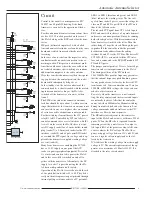
First, for commissioning, a jumper lead is connected to posi-
tion 1 of the two pole connector strip J2 and the FA-AS, by
way of the assembled DC cable and power supply
(13.8V/ 0.2A) is powered up. As long as the working voltage
is attached the microprocessor starts to work. This is con-
firmed by the short relay clicking and the subsequent flash-
ing of the LED’s. We’ll go into this again later.
Where all remains quiet and unlit then we have a wealth of
working voltages to check. 13V and 5V must be found at the
check points on the main board. If not then perhaps the fuse
is defective or not sitting correctly in its holder. Hook up a
transceiver or receiver to the antenna socket 1 and set the
frequency to 18.4320MHz in CW mode and a (faint)
tone should be heard. This is the sign that the microproces-
sor is working. If nothing is heard then it could be a defec-
tive quartz Q1 or one of its connections shorting to earth.
Before the commissioning can continue the aforementioned
“vital signs” of the microprocessor both audible and visible
must be present otherwise there is the task of finding and re-
placing the failed component.
If everything up to this point is in order then the FA-AS can
be disconnected from the power supply and the jumper wire
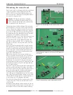
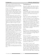
removed. Picture 30 shows how the connection of the FA-
AS to the transceiver and peripherals should be, for commis-
sioning only the pair of cables shown on the left hand side
are of interest.

Test of control by line voltage

Connect the FA-AS and the (powered down) Icom trans -
ceiver with the prepared control cable. There should be no
jumper leads plugged into the J2 connector strip. The appara-
tus now finds itself in test mode, where it will now check the
band information delivered from the transceiver and pro-
cessed by the microprocessor. This mode can also be useful
in some failure events. In test mode antennas will not be se-
lected or stored. The bi coloured LED’s on the front panel,
having nothing to do with antennas 1 to 4, now serve sepa-
rately as indicators. Immediately after switching on the
transceiver the FA-AS will also be powered up over
the control cable with 13.8V working voltage (see paragraph

assembly of control cables

’). LED 1 briefly lights up and

thereby signals the running through of the initialisation phase
of the programme, after which, in test mode, a precise com-
bination of LED’s light up in accordance with the applied
line voltage. This is set out in table 2.
Switching the transceiver to one of the amateur bands the ap-
propriate LED’s on the FA-AS must light up. At the test point
BSP (near the fuse holder) measure the line voltage delivered
from the transceiver against earth (test point M). This should
be within the range given by Ubsp in table 2. Of note is that
the WARC bands and the neighbouring classic bands are

Table 4. Set specific CI V address of some Icom
transceivers.

Transceiver                    CIV address

IC-7300                          94H

IC-7200                          76H

IC-7100                          88H

IC-7000                          70H

IC-7410                          80H

IC-718                            5EH

IC-706MKIIG                58H

IC-7400                          66H

IC-756ProIII                   6EH

IC-761                            1EH

IC-765                            2CH

IC-735                            04H

Table 3. Band dependant LED combinations in test
mode (CI V)

Band              

f

[MHz]              ANT 1      ANT 2       ANT 3      ANT 4

160m               0,1… 2,0         green                                            

80m                 2,1… 4,0                          green

60m                 4,1… 6,0         green        green

40m                 6,1… 8,0                                            green        

30m                 8,1… 12,0         green                           green        

20m                12,1… 16,0                          green          green        

17m                16,1… 19,0         green        green          green        

15m                19,1… 23,0                                                             green

12m                23,1… 26,0         green                                            green

10m                26,1… 30,0                          green                           green

6m                  30,1… 53,0         green        green                           green

4m                  53,1… 72,0                                            green        green

Table 2. Band dependant LED combinations in test
mode (line voltage only).

Band             

U

BSP

[V]       ANT 1        ANT 2         ANT 3         ANT 4

160m             6,7 … 8,3      green                                                   

80m               5,8… 6,6                          green

60 m              4,7… 5,7       green          green                                

40m               4,7… 5,7       green          green                                

30m               0,0… 1,1*                                            green           

20m               3,8… 4,6                          green            green           

17m               2,7… 3,7                                                                  green

15m               2,7… 3,7                                                                  green

12m               2,0… 2,6                          green                                green

10m               2,0… 2,6                          green                                green

6m                 1,2… 1,9*     grün            green                                green

4m                 1,2… 1,9*     grün            green                                green
* unspecified

Table 5.
Configuration of the FA-AS

Position                          Jumper                     Result

1                                      plugged                     working mode A

2                                      plugged                     working mode B

3                                      open                          9600 Baud

3                                      plugged                     1200 Baud

6                                      open                          transverter pwr 

10 %

6                                      plugged                     transverter pwr 

1 %

7                                      open                          transverter test routine off

7                                      plugged                     transverter test routine on

8                                      open                          CAT (S/E)

8                                      plugged                     CAT (E)

Содержание BX-7300

Страница 1: ...Transceivers with one antenna socket For use with up to 4 separate antennas each operating frequency may be automatically or manually selected also with an optional transverter Possibility of using se...

Страница 2: ...13 Function test 14 Control via line voltage 14 CAT interface test 15 Configuration 15 Working modes 15 Baud rate 15 Transceiver CIV address 15 Check routine for transverter mode 15 Control power for...

Страница 3: ...tions are followed The housing consists of base plate and top lid along with front and rear panels the joining of which is accomplished with the M3 tapped cubiform metal blocks provided Table 1 Techni...

Страница 4: ...e 4 BX 7300 180403 4 Antenna 1 Antenna 2 Antenna 3 Antenna 4 Socket1 Socket 2 Socket 3 Socket 4 Socket 5 Socket 6 Socket 7 Socket 8 Socket 9 Line voltage Hex code switch Picture 2 Circuit diagram of t...

Страница 5: ...o socket 7 is possible noting that the FA AS has no independent on off switch Operation of the FA AS is carried out with the aid of five push button switches S1 to S5 They lie di rectly on the micropr...

Страница 6: ...d to The positive connection is clearly marked on the board and on the component the negative side is usually marked gener ally the side with the shorter wire N B on the written side of the resistance...

Страница 7: ...pecial other function Pictures 3 to 7 show various stages of construction and can be used to show orientation For the first IC mount the 5V voltage regulator IC3 This is shown mounted in picture 8 Fir...

Страница 8: ...d plug and a twin core cable the DC supply should be assembled The sup plied fuse should be placed in its holder and the bench power supply set to 12V with a current threshold of 0 2A The voltage outp...

Страница 9: ...nd M3 6 nuts The sockets must be aligned as much as possible central to the rear panel holes and not touching as shown in picture 16 With the aid of an appropriate spanner the nuts on the cop per coat...

Страница 10: ...19 Subsequently when viewing the LED s from the front you must make sure that the longer of the two wires is located to the left From the length of the insulator material the installation height off...

Страница 11: ...CAT data circuit with the CI V connection socket Picture 24 The microprocessor must be fitted to the mounting in this position the indentation on the casing serves for the orienta tion With that the m...

Страница 12: ...d picture 28 Then the front panel and the rear panel with the fixed ele ments of the main board are screwed together don t forget the three M3 6 with nuts to fix the socket board Finally the whole ass...

Страница 13: ...line voltage transmit receive switching operating voltage 13 8V and earth Such plug connectors are available at e g 2 Picture 29 Example of the plug layout of the connecor cables be tween the FA AS a...

Страница 14: ...he bicoloured LED s on the front panel having nothing to do with antennas 1 to 4 now serve sepa rately as indicators Immediately after switching on the transceiver the FA AS will also be powered up ov...

Страница 15: ...CIV address of the FA AS doesn t match that of the transceiver When the testing of the control by line voltage and CAT in terface is complete the final configuration of the FA AS can be done Configur...

Страница 16: ...s checks that the FA AS has a valid line voltage about 2V connected 30m 6m or 4m shouldn t be selected and that the transceiver delivers a valid frequency 1 8 72MHz During the line voltage check ANT 2...

Страница 17: ...FA AS can also be reversed in that it may serve one antenna yet several transceivers or receivers Then the an tenna is connected to the TRX socket and the sets to the an tenna sockets Selection is po...

Страница 18: ...red green 4 Q1 Quartz 18 432MHz 1 R3 2 4k 1 R13 2 2k 1 R4 R8 R14 R15 R16 R17 4 7k 6 R1 R2 R7 4 7k 1 0 6W 3 R10 5 1k 1 0 6W 1 R18 R19 R20 R21 220 4 R5 R9 R22 10k 3 R6 R11 R12 1k 3 RN1 RN2 8 10k 2 S1 S...

Страница 19: ...BX 7300 180403 www funkamateur de 19 Attachments Automatic Antenna Selector Picture A1 Mounting plan of the Automatic Antenna Selector FA AS...

Страница 20: ...BX 7300 February 2018...

Отзывы: