


BX-7300 • 180403
© www.funkamateur.de
15
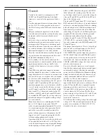
Configuration
Automatic Antenna Selector
gathered together with regards to the Icom line voltage.
When everything is in order, the next step is to test the CAT
interface. If you don’t want to use this then you may skip the
next section and all the installation.
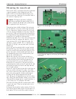
Testing the CAT control
The transceiver is switched off again and the power cable
for the FA-AS disconnected. The DC supply is again at-
tached to the bench power supply with 13.8V @ 0.2A (don’t
switch on yet!), that way it’s certain that the FA-AS has no
line voltage. Otherwise this would be picked up by the con-
troller and result in a not very obviously non functioning
CAT interface.
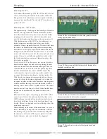
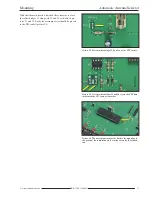
For testing the CAT interface the ‘remote’ socket on the
Icom transceiver should be connected by means of a regular
stereo audio cable with a 3.5mm jack plug attached at both
ends. The cable should be screened (see paragraph ‘
assem-
bly of control cables
’) if this fails or isn’t enough, a knock-
ing sound will be heard from the transceiver which is the
data traffic running on the CAT interface, in which case you
should invest in a higher quality cable. For this test there
should be no other apparatus connected to the CAT inter-
face.
In the transceiver setup menu, the CAT mode,
TRCV off
and
the transmission rate of 9600 Baud should be selected. There
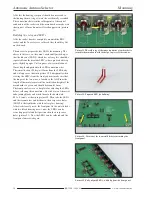
shouldn’t be any jumper leads plugged into J2. Finally the
two encoder chips must be married to the address of the con-
nected Icom transceiver. S6 is for the first place with S7 be-
longing to the second. The transceivers CIV address can be
found in the handbook or in table 4. This address can be
changed for other new apparatus via the transceiver set up
menu, if that’s the case then it is self explanatory that the ad-
dress to the FA-AS must be changed.
After connecting the transceiver to the DC power the LED’s
must again light up according to table 3. There is an un-
equivocal combination for each band and here no undefined
state or misinterpretation of commands can appear. If the
CAT control doesn’t work the overall installation should be
checked before making any further adjustments to the
transceiver and FA-AS. During this operation there must be
a perceptible data impulse trace on an oscilloscope at J4 and
J3. Failing this it could be a defective connecting cable.
If this is of no further help then the transceiver should be put
into configuration mode and TRCV turned to ‘
on
’ then ev-
erything retested. If the control now works it may perhaps
be the selected CIV address of the FA-AS doesn’t match that
of the transceiver.
When the testing of the control by line voltage and CAT in-
terface is complete, the final configuration of the FA-AS can
be done.
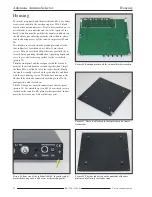
Configuration
The necessary installations are dependant on the antennas
and apparatus configuration of the user and are achieved, es-
sentially, by plugging jumper leads into the J2 connector
strip. Alterations in any other case requires the apparatus to
be unscrewed.
Important Notice:
The configuration of the FA-AS is read by the micro proces-
sor only after the apparatus is switched on. Between times
adjustments in a switched on state will only take effect after
the apparatus has been switched off and then on again.
Working modes
The FA-AS has two modes of working. In mode A, all four
antennas are equal and each may be individually pro-
grammed for automatic mode as desired. Working mode B
takes with it the following variations. Select antenna 1 so the
FA-AS sees this as a receiving antenna and the signal sent
from the transceiver ACC socket is rated as SEND or
HSEND by the FA-AS. When the transceiver is transmitting
(signal PTT on socket 8), the FA-AS switches to antenna 2
as the transmit antenna. By arranging antennas 2 to 4 on am-
ateur radio bands the FA-AS retains working mode A.
Working mode A can be selected by jumper leads in position
1 and working mode B with jumpers in position 2 (table 5).
If the CIV interface isn’t going to be used then the thre fol-
lowing installations may be ignored.
Baudrate
The CI V Baud rate is decided by plug bridges at position 3.
A plugged jumper gives 1200 Baud and unplugged it gives
9600 Baud. One should choose the highest appropriate Baud
rate that the connected transceiver will support, which in
most cases will be 9600 Baud.
Transceiver CIV address
Every Icom transceiver has a set specific CIV address. This
means that several parallel connected receivers or trans -
ceivers may be controlled independantly of one another by a
command set or PC software, it also facilitates data delivery.
This address is given in the transceivers handbook (see also
the section on CAT-control) and is installed on the FA-AS
main board by the encoders S6 and S7.
Check routine for transverter mode
With active CAT control the FA-AS offers the possibility in
conjunction with the switching of transceiver connections of
a transverter which automatically reduces and regulates
power when the 10m amateur radio band is selected. This of
course if the transceiver being used supports such powering
command requirements. Operating the TRV button will start
up the checking and installation routine and, if the result is
fault free, resolve the switching. When, for example, another
Содержание BX-7300
Страница 20: ...BX 7300 February 2018...


