


© www.funkamateur.de
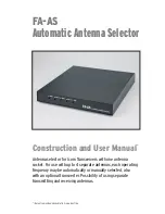
Automatic Antenna Selector
Mounting
10
BX-7300 • 180403
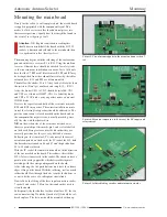
After this the housing rear panel should be unscrewed so
that during the next stage it won’t be accidentally scratched.
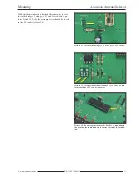
The connections between the solder points of the central
conductors of the sockets and the main board are made with
short pieces of 1mm diameter silvered copper wire (picture
18).
Building the relay and LED’s
After the socket board is completely mounted the BNC
socket and the five relays are soldered, they should lay flat
on the board.
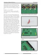
Then next is to prepare the five LED’s for mounting. The
advice in this case, so they aren’t accidentally mixed up, is
that the blue one (LED 5) which has a clear glass should be
separated from the bicolour LED’s whose plastic bodies ap-
pears slightly opaque. Cut ten pieces of wire insulation of
22mm length and push onto the LED connection wires.
These must be bent 90 deg. att 12mm from the LED body
and will appear as shown in picture 19. Subsequently when
viewing the LED’s from the front you must make sure that
the longer of the two wires is located to the left. From the
length of the insulator material the installation height off the
main board is a given and should be around 10mm.
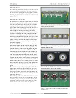
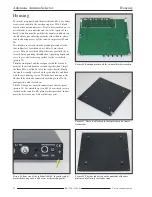
The front panel serves as a template for adjusting the LED’s
before soldering the connections. Now take two of the metal
cube joining blocks and attach them to the board with
M 3
×
4 screws as shown in picture 20. Then take the LED’s
and their connectors and fit them to their respective holes
(LED 5 is the light diode with the clear glass housing).
Afterwards loosely screw the front panel to the metal blocks
with two black housing screws, now the LED’s can be
evened up parallel and best positioned in their respective
holes (picture 21). Now the LED’s can be soldered and the
front panel unscrewed again.
Picture 21. Fully aligned LED’s, with help from the front panel.
Picture 19. Prepared LED for building.
Picture 20. Position of the two metal blocks for attaching the
front panel.
Picture 18. The solder tag of the inner conductor of each socket is
joined to the main board with the help of a piece of silvered wire.
Содержание BX-7300
Страница 20: ...BX 7300 February 2018...


