


© www.funkamateur.de
Automatic Antenna Selector
Mounting
6
BX-7300 • 180403
Mounting the main board
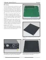
If only for the sake of a well completed job, the circuit board
is supplied pre printed with the component layout. This
makes it a little easier to solder the additional pieces into
their correct positions, equally how those might be found in
the event of investigating a fault.
Attention:
N.B. Regular constructors reading this
should bear in mind that if the board with the SO 239
sockets is finished and soldered to the main board then
it’s expedient to solder the relays first.
The mounting begins with the soldering of the surface com-
ponents in this case resistors R1 to R22. Using the multime-
ter set as Ohmeter these should be checked for safetys sake
so that no erroneous substitution can occur. Just a little note
here that the 4.7 KΩ metal film resistors R1 R2 and R7 may
be distinguished from the carbon film resistors by their blue
coloured base. R23 and R24 are left unmounted.
Then follow the chokes L1 to L7 they look a little fatter than
the resistors. (Don’t get confused and swap R18 … R21!)
After, the diodes VD 1 to VD 9 should be installed. VD1
and VD2 are 1Adiodes 1N4007, VD3 is a Schottky diode
and VD7 a 5.1VZ diode, or by any other name, a universal
1N4148 diode.
Next are the capacitors and both of the resistance networks
RN1 and RN2 in sequence. The correct installation orienta-
tion of the electrolytic capacitors should be adhered to. The
positive connection is clearly marked on the board and on
the component the negative side is usually marked, gener-
ally the side with the shorter wire.
N.B.
on the written side of the resistance network cases
there is a printed spot, this marks pin 1 and is also labelled
on the board. Here great care must be taken that they are
correctly positioned as they are very difficult to remove.
Following on, the transistor VT1 (take note of the correct
orientation printed on the board), the IC socket for IC1, both
the haexadecimal encoders S6 and S7 and the push buttons
S1 to S5 can be soldered.
With the IC socket, the indentation should be in the direction
of the one marked on the board. This reduces the risk that
IC1 is later set incorrectly in the socket. The encoders have a
point on the casing upperside which after soldering must
match up with the corresponding mark on the board.
After soldering, the five push buttons must have their frame
edges sitting on the board. With the soldering, not too much
solder should flow through the holes towards the buttons so
as not to be the cause of a subsequent short circuit.
Now follows the fitting of the three input connectors socket
7 socket 8 and socket 9. Here too, their undersides need to
sit on the board.
Subsequently the fuse holder for the cut out fuse F1, the two
row connector strip J2 and the Quartz xtal Q1 should be sol-
dered in place. The last one should be mounted with an ap-
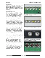
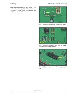
Picture 3. View of mounted parts in the area of antenna sockets 7
to 9.
Picture 4. Mounted components in the area of the DC supply and
relay control.
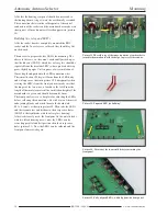
Picture 5. Soldered coding switches and resistance networks
Содержание BX-7300
Страница 20: ...BX 7300 February 2018...


