


BX-7300 • 180403
© www.funkamateur.de
3
Introduction
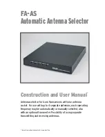
Automatic Antenna Selector
When operating middle to low price range transceivers
with only one antenna connection it is often desirable to
employ the use of an antenna selector switch. The first
type is the manually configured variety which will re-
quire the carrying out of diverse specialist adjustments.
Considerably more convenient however is to use an addi-
tional external piece of equipment that, depending on the
actual band in use, automatically switches to the desired
antenna.
This was the starting point (as fully described at [1]) for the
FA-AS kit. It was conceived for the Icom IC-7300 (hence
the order number BX-7300) and also works well with other
Icom transceivers. The control for the antenna selection
comes from the Icom transceivers provided line voltage
which will vary according to the selected Amateur Radio
band. As a further option it is possible to connect both
pieces of equipment over the CIV interface (CAT) so that
operating on classic SW and WARC bands and monitoring
on VHF may be distinguished. In addition there is the con-
venience of connection between antenna selector and
transverter output.
The kit consists of main and socket boards together with all
the required kit parts and also a printed metal housing. It
comes with components exclusively wired for the kit.
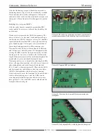
The requirements for building are also straightforward when
the corresponding kit building instructions are followed. The
housing consists of base plate and top lid along with front
and rear panels, the joining of which is accomplished with
the M3 tapped cubiform metal blocks provided.
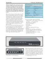
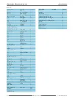
Table 1. Technical data
Suitable controller Icom transceiver
Control information Line voltage or CIV command
HF connections up to four antennas and one transverter
Z = 50Ω, unbalanced
HF power ≤ 150W
Frequency range 0 … 72MHz*
Attenuation ≤ 0.1dB
SWR ≤ 1.2
Antenna memory EEPROM
Working voltage 12 … 15V
Current drain approx. 100mA @ 13.8V
Dimensions (W
×
H
×
D) 238
×
33
×
240 mm
3
Weight ≈ 1.8kg
* Automatic mode 1.8 … 72MHz
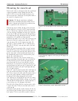
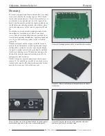
Picture 1a. Front view of the fully built FA -AS
Tools and materials required for building:
– soldering iron 60W … 80W with pencil type fine point tip
along with 0.5 … 1mm. Resin core solder
– 100W soldering iron with flat tip
– side cutters for electronics
– flat nose pliers
– flat tip screwdriver
– small file
– spanner SW18 to mount the SO 239 sockets
– multimeter
– 50Ω dummy load (with temporary 100W capacity)
– bench power supply 10 … 15V @ 0.2A with adjustable
voltage and current thresholds
– DC supply cable with 2.1 mm hollow round plug
(plug connector with kit parts)
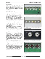
Before mounting the board one should check and verify the
contents of the kit with the parts list provided. It contains in-
formation on the labelling of kit parts. Make sure to sort the
resistors to avoid accidental substitution during the build. If
sometimes the colour coding rings are not so easily identifi-
able then it is recommended to use an Ohmeter to check the
value, otherwise, poor performance due to an incorrect resis-
tor is subsequently not so easy to trace.
Picture 1b. Rear view of the fully built FA -AS
Содержание BX-7300
Страница 20: ...BX 7300 February 2018...


