1-13-14
E3TFGTR
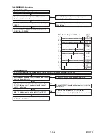
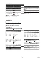
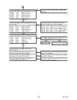
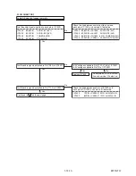
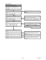
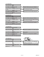
FLOW CHART NO.3
FLOW CHART NO.4
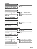
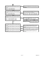
Cassette tape can not be loaded.
Cassette tape is ejected right after the loading.
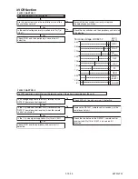
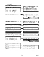
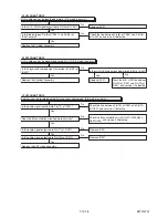
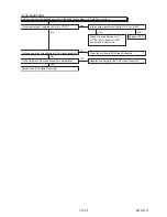
FLOW CHART NO.5
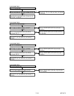
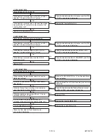
Cassette tape can not be ejected.
When loading a cassette tape, on Pin(100) of IC501,
does the "L" pulse switch to the "H" pulse?
When loading a cassette tape, on Pin(100) of IC501,
does the "L" pulse switch to the "H" pulse?
When loading a cassette tape, on Pin(4) of IC501,
does the "L" pulse switch to the "H" pulse?
When pressing the eject button, does the Capstan
Motor start rotating?
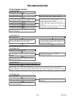
Refer to "FLOW CHART NO.6 " <The Capstan Motor
does not rotate>.
Replace IC501.
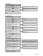
While the Capstan Motor is rotating, is the Takeup
Reel rotating?
Is the Loading Motor rotating?
While the Takeup Reel is rotating, is the reel pulse
signal inputted to Pin(80) of IC501?
While the reel pulse signal is inputting, is "L" pulse
outputted to Pin(81) of IC501?
Is the specified voltage (approximately 13V)
outputted to the terminal of the Loading Motor Unit?
When loading a cassette tape, does the LD-SW
operate normally?
When loading a cassette tape, is the specified voltage
(approximately 13V) outputted to the terminal of the
Loading Motor Unit?
Check the line between the start sensor and Pin(100)
of IC501, and service it if defective.
Replace IC501.
Yes
Yes
Yes
Yes
Yes
Yes
Yes
Yes
Yes
Yes
Yes
No
Check the line between the start sensor and Pin(100)
of IC501, and service it if defective.
Check the line between the end sensor and Pin(4)
of IC501, and service it if defective.
Check the line between the LD-SW(SW507) and Pin(9)
of IC501, and service it if defective.
Check the line between the Takeup Reel sensor and
Pin(80) of IC501, and service it if defective.
No
No
No
No
No
No
No
No
No
No
Replace the Loding Motor Unit.
Check the Reel Disc or Clutch Assembly, and service it
if defective.
Check the Cam Gear or Rack Assembly, etc.,
and service it if defective.
Replace the Capstan Motor Unit.
Replace the Loading Motor Unit.
Replace the Capstan Motor Unit.
Содержание TD6D-M101
Страница 16: ...1 7 4 E3TFGDC S 24 S 23 S 25 18 VCR Chassis Unit 17 Power SW CBA Desolder Lead with blue stripe Fig D7...
Страница 61: ...1 15 3 E3TFGSCAV1 AV 1 10 Schematic Diagram VCR Section...
Страница 63: ...1 15 5 E3TFGSCAV3 AV 3 10 Schematic Diagram VCR Section...
Страница 64: ...1 15 6 E3TFGSCAV4 AV 4 10 Schematic Diagram VCR Section...
Страница 65: ...1 15 7 E3TFGSCAV5 AV 5 10 Schematic Diagram VCR Section...
Страница 66: ...1 15 8 E3TFGSCAV6 AV 6 10 Schematic Diagram VCR Section...
Страница 67: ...1 15 9 E3TFGSCAV7 AV 7 10 Schematic Diagram VCR Section...
Страница 68: ...1 15 10 E3TFGSCAV8 AV 8 10 Schematic Diagram VCR Section...
Страница 69: ...1 15 11 E3TFGSCAV9 AV 9 10 Schematic Diagram VCR Section...
Страница 70: ...1 15 12 E3TFGSCAV10 AV 10 10 Schematic Diagram VCR Section...
Страница 73: ...1 15 15 Rear Jack Schematic Diagram VCR Section E3TFGSCRJ...
Страница 79: ...1 15 21 E3TFGSCD6 DVD HDD Main 6 7 Schematic Diagram DVD HDD Section...
Страница 81: ...1 15 23 E3TFGSCDTV DTV Module Schematic Diagram DVD HDD Section...
Страница 82: ...1 15 24 E3TFGSCSATA SATA Schematic Diagram...
Страница 107: ...TD6D M101 E3TFGEH 2013 04 22...


