Fig 6-2 Rel ationship bet ween environment and Carrier frequency
Relationship bet ween Model and Carrier frequency
This function is mainly used t o i mprove the motor operating noise a nd invert er int erference to external .
The a dvantages of using high carrier frequency: relatively ideal current wave shape, less harmonic
current wave and low motor nois e;
The disadvantages of us ing high carrier frequency: increas ed switch loss and inverter temperature rises,
affecting invert er output capacit y so that it s hould be operated at derating under hi gh carri er freque ncy
conditions; in the me an time, inverter leakage current and it s electroma gnetic interference to external are
i ncreased.
The situations of usi ng l ow carrier frequency is on the contrary. Too low carrier frequency can c ause
operation unstable, t orque reduced a nd even oscillation at low frequenc y.
W hen inve rter is fact ory rele ased, its carrier frequenc y has been set properly. Generally the user does
not need to modify t his parameter.
Carrier
frequency
Electron magnetic
noise
Caco phon y,
Leakage current
Heat radiation
1KHz
10KHz
15KHz
larg e
small
large
sma ll
larg e
small
Carrier frequ ency
Model
Factory
set ting
(KHz)
B:0 . 4 k W~1 1 K W
P:0 . 7 5 kW~1 5 KW
1 5
1
8
B:1 5 k W~55 K W
P:1 8 . 5 kW~7 5 KW
8
1
4
B:7 5 k W~30 0 K W
P:9 0 k W~31 5 K W
6
1
2
M in carrier
freque ncy
(KHz)
Max carrier
f requ ency
(KHz)
F0.11
Carr ier frequ ency s etti ng
1.0
15 .0kHz
~
Set by
model
Functio n
Cod e
Name
Setting Range
Default
Value
Chapter 6 Para meter Description
DZB Series
-3 8 -
0: Operating at default direction. W hen the inverter is power connected, it operates at the actual direction.
1: Operating at reverse di recti on. B y means of changing the function code, the motor rota ti ng di rec ti on can
be changed wi thout changing any other parameters, whi ch is equiva lent to change the motor rotat ing
direct ion by exchanging any two of mot or cabl es (U, V, W).
2: Forbid i nverse operating. Forbidding inverter inverse operation is suitable to specific a pplicat ion that
inve rse operat ing is forbidden.
Note: After the parameters are initializ ed, the mot or oper ati ng direction can be res tored t o be it s
original s tate. Be caution t o u se it in th e case that chan gin g motor rotating direction i s for bidde n after
the system commissioning is completed.
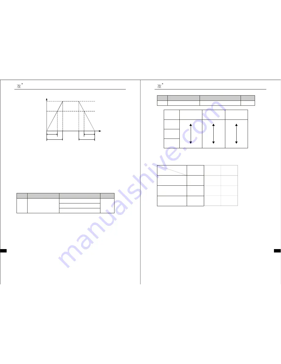
Fig 6-1 Ac cel erati on a nd Deceleration time diagram
Output frequency f
f
m ax
f
s e t
actu al acc e.
ti me
set a cce.t ime
a ct ual d ece .
t ime
se t dec e.time
Time t
When the set freque ncy is equal to the maximum frequency, t he actual Acceleration/Decelera tion time
are equal to the set Accelera ti on/Deceleration time.
When the set freque ncy is less than the maxi mum frequency, the actual Acceleration/Deceleration time
are les s than t he set Accele rat ion/ Dec eleration time.
Ac tual Acceleration /De cel era ti on t ime = s et Accel eration/De celeration t ime
(s et frequency/max.
freque ncy)
DZB200&300 ser ies inverter has 2 groups of Accel eration/Decelerat ion time.
1st group: F0.08, F0.09;
2nd group: F4.00, F4.01;
The Accel eration /Deceleration time can be chosen through mult ifunction di git al i nput te rmina l (F2 Group).
×
F0.10
Opera tion direc tion
selection
0
Operating at default direc tion
:
1
Operating at reverse direction
:
2
NO inv ers e operating
:
2
Function
Code
Nam e
Setting Range
Default
Value
Cha pter 6 Parameter D es cription
DZB Series
- 37-
BLUE ELEPHANT BLUE ELEPHANT BLUE ELEPHANT BLUE ELEPHANT
BLUE ELEPHANT BLUE ELEPHANT BLUE ELEPHANT BLUE ELEPHANT
BLUE ELEPHANT BLUE ELEPHANT BLUE ELEPHANT BLUE ELEPHANT
BLUE ELEPHANT BLUE ELEPHANT BLUE ELEPHANT BLUE ELEPHANT
BLUE ELEPHANT BLUE ELEPHANT BLUE ELEPHANT BLUE ELEPHANT
BLUE ELEPHANT BLUE ELEPHANT BLUE ELEPHANT BLUE ELEPHANT


