Bus vo ltage
St all Ove r-volt ag e poin t
Out pu t f r e qu e nc y
Tim e t
Tim e t
During the inverter decelerat ion, the load inertia may cause the actual motor speed drop rate l ower than
t he output frequency drop rate, and thereby the motor generates electricity and feeds it back to the inverter,
caus ing the i nverter bus voltage going up and even bus over-voltage breakdown which t hen can cause
i nverter tripping if no provis ion i s made.
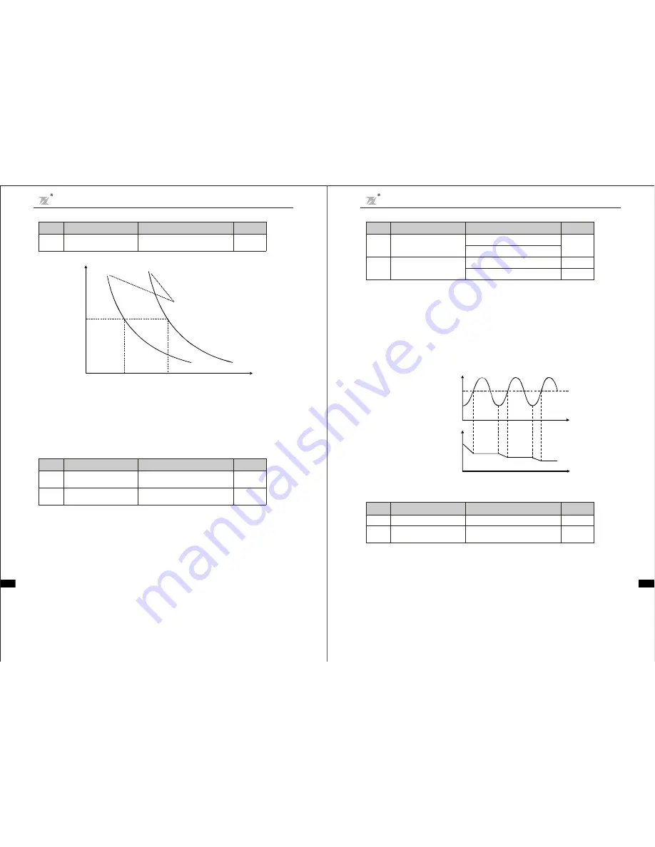
Over-voltage stall protection function is to detect t he bus voltage and compare it with the sta ll over-
voltage point defined by F5.05 (relative to t he standa rd bus voltage) . If i t exceeds the over-voltage stall
point, inverter output frequency s top going down, and when the next bus voltage detected is lower than
t he over-vol tage stal l point, t he inverter continues to decelerate, as shown by followi ng figure:
Fig.6-22 O ver-voltage Stall Funct ion
W hen inve rter is runni ng, the actual climbing ra te of motor speed is lowe r than cl imbing rate of out put
frequency because load is too big. If you don't ta ke any action, it will cause over current faul t in
acceleration then inverter will t rip.
Over-current stal l protect ion function is t o de tect output current and compare it wit h the current limit
defined by F5.06. If it exceeds the c urrent limit, output frequency drop down according to F5.07. When it
s how tha t output current is lower tha n l imit current, inverter wil l remain norma l operation.
F5.04
Over -voltage
Stall Pr otectio n
0
pr ohibit
:
1
allow
:
0
F5.05
Over -voltage Stall
Protection Vo ltage
110
150%(3 80V)
~
12 0%
110
150%(2 20V)
~
115 %
Functio n
Cod e
Name
Setting Range
Default
Value
F5.06
Over -current s tall s etting
80
20 0%
~
15 0%
F5.07
Over -current ga in settin g
to avoi d of stalling
0
100
~
20
Functio n
Cod e
Name
Setting Range
Default
Value
Chapter 6 Para meter Description
DZB Series
-6 6 -
Fig.6-21 Motor Overload Protect ion Current
The val ue can be de termined by fol lowing equat ion:
Motor overl oad protection current = (maximum current/ rat ed current)
100%
It is mai nly applied to the cases that bi g inver ter drives small motor, requiring to corre ctly set up this
funct ion to protect the mot or.
×
If the inst ant power-down drop rate is set to be 0, the instant power-down res tart function is invalid.
Instant power-down frequency drop poi nt: it i s indicting when the bus voltage, after the power net work
is down and drops to the instant power-down frequency drop point, the invert er sta rts to decreas e the
opera ti on frequency based on the insta nt power-down frequency drop rate, enabli ng the mot or to genera te
el ectri city which is fed back t o ke ep the bus voltage, and thus ensuring t he inverter i s operating normall y
till inverter power is on again.
Impor tant: Adj us ting t he se t wo parameters properly can magnificently achieve the power networ k
switching ins tead of causi ng inve rter prot ection and thus c ausing production shu tdown.
7 0%
100%
140%
2 00%
Current
1 m inute
Time
Motor Overload Pro tection Current
F5.0 1
Motor Ove rload
Pro tection Current
20.0%
120.0%
(mo tor rated cu rren t)
~
100.0%
Function
Code
Nam e
S etting Range
D efault
Value
F 5.02
Power- down F requ ency
Drop Poi nt
70.0
110.0 %(standard bus
voltage)
~
80.0%
F5.03
Ins tant p owe r-down
Frequ ency drop rate
0.00Hz
99.99Hz
~
0.0 0Hz
Function
Code
Nam e
S etting Range
D efault
Value
Cha pter 6 Parameter D es cription
DZB Series
- 65-
BLUE ELEPHANT BLUE ELEPHANT BLUE ELEPHANT BLUE ELEPHANT
BLUE ELEPHANT BLUE ELEPHANT BLUE ELEPHANT BLUE ELEPHANT
BLUE ELEPHANT BLUE ELEPHANT BLUE ELEPHANT BLUE ELEPHANT
BLUE ELEPHANT BLUE ELEPHANT BLUE ELEPHANT BLUE ELEPHANT
BLUE ELEPHANT BLUE ELEPHANT BLUE ELEPHANT BLUE ELEPHANT
BLUE ELEPHANT BLUE ELEPHANT BLUE ELEPHANT BLUE ELEPHANT


