B-16
SPARC Enterprise M8000/M9000 Servers Service Manual • October 2012
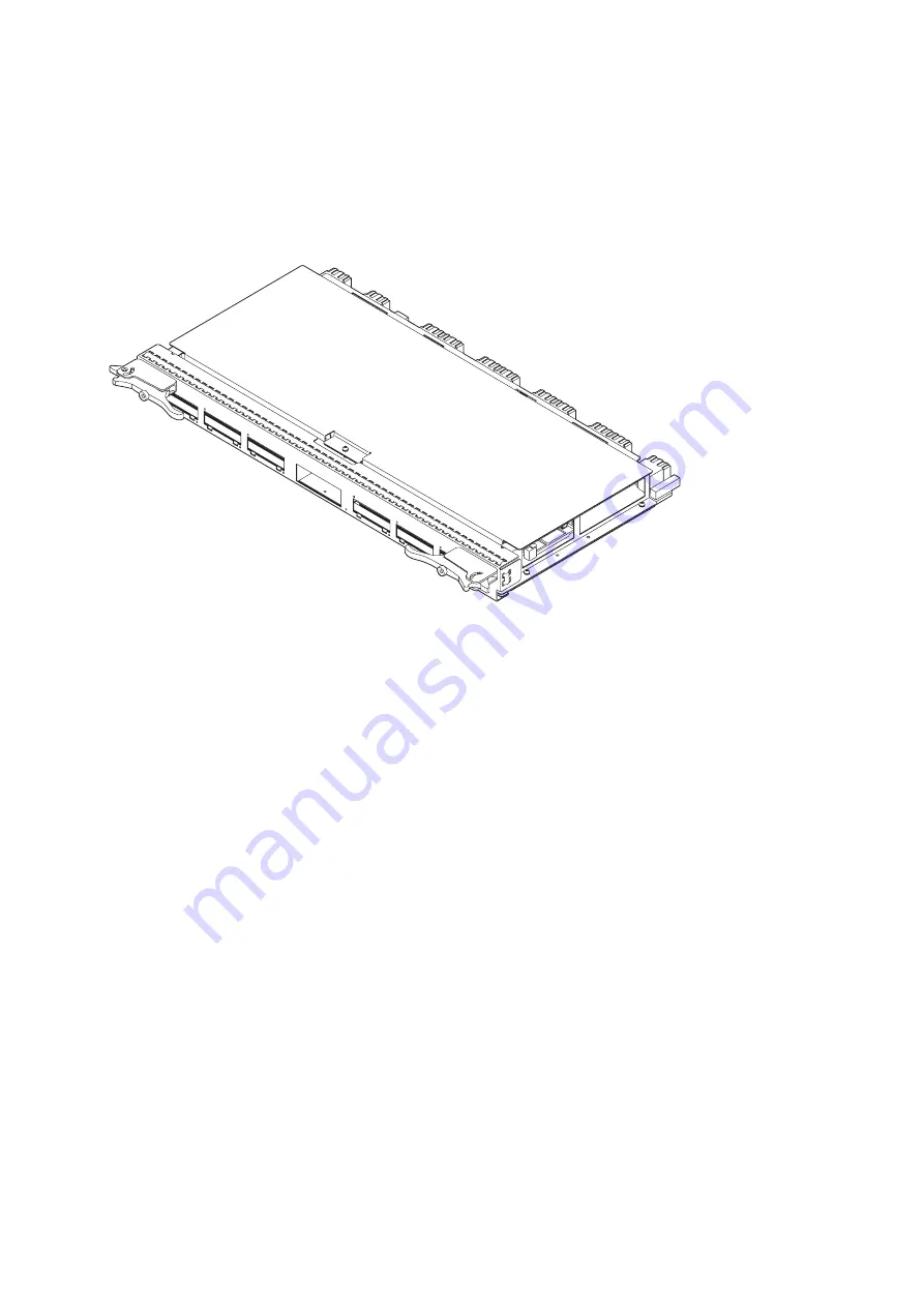
FIGURE B-9
Crossbar Unit (XBU_B)
The XBU has the following characteristics.
■
Only cold replacement is available for the XBU.
■
In the M9000 server (with an expansion cabinet) model, control over the expansion
cabinet is done by connecting the XBUs of both base cabinet and expansion cabinet with
cables.
■
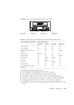
The XBU has a normal mode and a degraded mode. In normal mode, all eight sets
operate; and in degraded mode in which a failure has occurred, the four sets containing
the failed set are disconnected, and operation continues with the remaining four normal
sets. If an XB fails, the system is shut down to disconnect the four sets including the
failed XB, and it is then automatically recovered.
■
A dedicated LSI chip is used for the crossbar switch (XB).
■
For the bus connecting CMU and XBU, a high-speed link is used.
■
For the bus connecting the IOU and XBU and the bus connecting XBUs of the base
cabinet and expansion cabinet, a high-speed link is being used.
■
The XBU has a label bearing the printed component number and manufacture's serial
number.
Содержание SPARC Enterprise M8000
Страница 4: ......
Страница 15: ...Contents xv Index Index 1 ...
Страница 16: ...xvi SPARC Enterprise M8000 M9000 Servers Service Manual October 2012 ...
Страница 22: ......
Страница 27: ...Chapter 1 Safety and Tools 1 5 M9000 Server Front View ...
Страница 29: ...Chapter 1 Safety and Tools 1 7 Power Supply Unit PSU ...
Страница 37: ...Chapter 1 Safety and Tools 1 15 FIGURE 1 10 M9000 Grounding Port Connection Locations Rear View ...
Страница 38: ...1 16 SPARC Enterprise M8000 M9000 Servers Service Manual October 2012 ...
Страница 54: ...2 16 SPARC Enterprise M8000 M9000 Servers Service Manual October 2012 Removing an I O unit IOU ...
Страница 88: ...2 50 SPARC Enterprise M8000 M9000 Servers Service Manual October 2012 ...
Страница 137: ...Chapter 4 FRU Replacement Preparation 4 43 FIGURE 4 12 Magnified View of Part A M8000 Rear View ...
Страница 145: ...Chapter 4 FRU Replacement Preparation 4 51 FIGURE 4 19 Magnified View of Part B M8000 Rear View ...
Страница 148: ......
Страница 154: ...5 6 SPARC Enterprise M8000 M9000 Servers Service Manual October 2012 ...
Страница 180: ...6 26 SPARC Enterprise M8000 M9000 Servers Service Manual October 2012 FIGURE 6 16 CMU Guide Lock Enlarged ...
Страница 204: ...7 12 SPARC Enterprise M8000 M9000 Servers Service Manual October 2012 FIGURE 7 7 Removing the IOU Rear of M8000 1 1 2 3 ...
Страница 205: ...Chapter 7 I O Unit IOU Replacement 7 13 FIGURE 7 8 Removing the IOU Front of M9000 1 1 2 3 ...
Страница 219: ...Chapter 8 FAN Unit Replacement 8 3 FIGURE 8 2 FAN Mounting Locations Rear of the M8000 FAN_B 2 7 7 5 6 4 3 2 ...
Страница 227: ...Chapter 8 FAN Unit Replacement 8 11 FIGURE 8 9 Removing the FAN Unit Rear of M8000 1 2 ...
Страница 251: ...Chapter 10 Operator Panel Replacement 10 3 FIGURE 10 2 OPNL Mounting Location Front of the M9000 Base Cabinet OPNL ...
Страница 256: ...10 8 SPARC Enterprise M8000 M9000 Servers Service Manual October 2012 ...
Страница 272: ...11 16 SPARC Enterprise M8000 M9000 Servers Service Manual October 2012 ...
Страница 312: ...13 30 SPARC Enterprise M8000 M9000 Servers Service Manual October 2012 ...
Страница 340: ...15 14 SPARC Enterprise M8000 M9000 Servers Service Manual October 2012 ...
Страница 358: ...17 10 SPARC Enterprise M8000 M9000 Servers Service Manual October 2012 ...
Страница 361: ...Chapter 18 AC Section Replacement 18 3 FIGURE 18 2 ACS Mounting Location Front of the M9000 Base Cabinet ACS_B ...
Страница 367: ...Chapter 18 AC Section Replacement 18 9 FIGURE 18 5 Removing the AC Section Front of the M9000 1 2 1 ...
Страница 370: ...18 12 SPARC Enterprise M8000 M9000 Servers Service Manual October 2012 ...
Страница 380: ...19 10 SPARC Enterprise M8000 M9000 Servers Service Manual October 2012 ...
Страница 383: ...Chapter 20 Backplane Replacement 20 3 FIGURE 20 2 BP Mounting Locations Front of the M9000 Base Cabinet BP_B ...
Страница 389: ...Chapter 20 Backplane Replacement 20 9 FIGURE 20 4 Preparation for Accessing BP_A Rear of the M8000 ...
Страница 392: ...20 12 SPARC Enterprise M8000 M9000 Servers Service Manual October 2012 FIGURE 20 6 Removing the BP Rear of the M8000 ...
Страница 409: ...Chapter 20 Backplane Replacement 20 29 FIGURE 20 16 Removing the FANBP Rear of the M8000 ...
Страница 410: ...20 30 SPARC Enterprise M8000 M9000 Servers Service Manual October 2012 FIGURE 20 17 Removing the FANBP Front of M8000 ...
Страница 415: ...Chapter 21 Sensor Unit Replacement 21 3 FIGURE 21 2 SNSU Mounting Location Front of the M9000 Base Cabinet SNSU ...
Страница 422: ...21 10 SPARC Enterprise M8000 M9000 Servers Service Manual October 2012 ...
Страница 425: ...Chapter 22 Media Backplane Replacement 22 3 FIGURE 22 2 MEDBP Mounting Location Front of the M9000 Base Cabinet MEDBP ...
Страница 430: ...22 8 SPARC Enterprise M8000 M9000 Servers Service Manual October 2012 FIGURE 22 4 Removing the MEDBP Front of the M8000 ...
Страница 435: ...Chapter 23 Switch Backplane Replacement 23 3 FIGURE 23 2 SWBP Mounting Location Front of the M9000 Base Cabinet SWBP ...
Страница 439: ...Chapter 23 Switch Backplane Replacement 23 7 FIGURE 23 4 Removing the SWBP Rear of the M8000 ...
Страница 442: ...23 10 SPARC Enterprise M8000 M9000 Servers Service Manual October 2012 ...
Страница 460: ...24 18 SPARC Enterprise M8000 M9000 Servers Service Manual October 2012 ...
Страница 484: ...25 24 SPARC Enterprise M8000 M9000 Servers Service Manual October 2012 ...
Страница 494: ...A 10 SPARC Enterprise M8000 M9000 Servers Service Manual October 2012 ...
Страница 537: ...Appendix B Components B 43 FIGURE B 38 FAN Backplane FANBP_B FIGURE B 39 FAN Backplane FANBP_C ...
Страница 544: ...C 4 SPARC Enterprise M8000 M9000 Servers Service Manual October 2012 ...
Страница 552: ...D 8 SPARC Enterprise M8000 M9000 Servers Service Manual October 2012 ...


