25-1
C H A PT E R
25
Addition, Deletion, and Upgrade of
FRU
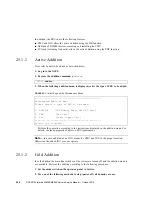
This chapter firstly explains the procedures for adding the CPU/memory board unit (CMU),
DIMM, I/O unit (IOU), hard disk drive (HDD), PCI card, tape drive unit (TAPEU), CPU
module, fan unit (FAN) and power supply unit (PSU) to the server. Secondly, this chapter
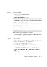
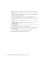
explains the procedures for deleting CMU, IOU and PCI card from the server.
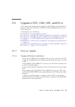
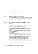
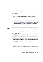
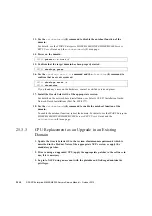
This chapter also explains the procedures of upgrading CPU, CMU and IOU.
■
Section 25.1, “Addition” on page 25-1
■
Section 25.2, “Deletion” on page 25-4
■
Section 25.3, “Upgrade of CPU, CMU, IOU, and IOUA” on page 25-7
25.1
Addition
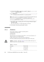
The procedure of addition is intended for the following FRUs:
■
CPU/memory board unit (CMU)
■
DIMM
■
I/O unit (IOU)
■
Hard Disk Drive (HDD)
■
PCI card (PCI)
■
Tape Drive Unit (TAPEU)
■
CPU module (CPUM)
■
Fan unit
■
PSU
The FRUs allow for active addition, and cold addition, as well as regular replacement. Based
on certain conditions, you may need to update the software and firmware, as well as stop the
domain. For details, see
Section 25.3, “Upgrade of CPU, CMU, IOU, and IOUA” on
.
Содержание SPARC Enterprise M8000
Страница 4: ......
Страница 15: ...Contents xv Index Index 1 ...
Страница 16: ...xvi SPARC Enterprise M8000 M9000 Servers Service Manual October 2012 ...
Страница 22: ......
Страница 27: ...Chapter 1 Safety and Tools 1 5 M9000 Server Front View ...
Страница 29: ...Chapter 1 Safety and Tools 1 7 Power Supply Unit PSU ...
Страница 37: ...Chapter 1 Safety and Tools 1 15 FIGURE 1 10 M9000 Grounding Port Connection Locations Rear View ...
Страница 38: ...1 16 SPARC Enterprise M8000 M9000 Servers Service Manual October 2012 ...
Страница 54: ...2 16 SPARC Enterprise M8000 M9000 Servers Service Manual October 2012 Removing an I O unit IOU ...
Страница 88: ...2 50 SPARC Enterprise M8000 M9000 Servers Service Manual October 2012 ...
Страница 137: ...Chapter 4 FRU Replacement Preparation 4 43 FIGURE 4 12 Magnified View of Part A M8000 Rear View ...
Страница 145: ...Chapter 4 FRU Replacement Preparation 4 51 FIGURE 4 19 Magnified View of Part B M8000 Rear View ...
Страница 148: ......
Страница 154: ...5 6 SPARC Enterprise M8000 M9000 Servers Service Manual October 2012 ...
Страница 180: ...6 26 SPARC Enterprise M8000 M9000 Servers Service Manual October 2012 FIGURE 6 16 CMU Guide Lock Enlarged ...
Страница 204: ...7 12 SPARC Enterprise M8000 M9000 Servers Service Manual October 2012 FIGURE 7 7 Removing the IOU Rear of M8000 1 1 2 3 ...
Страница 205: ...Chapter 7 I O Unit IOU Replacement 7 13 FIGURE 7 8 Removing the IOU Front of M9000 1 1 2 3 ...
Страница 219: ...Chapter 8 FAN Unit Replacement 8 3 FIGURE 8 2 FAN Mounting Locations Rear of the M8000 FAN_B 2 7 7 5 6 4 3 2 ...
Страница 227: ...Chapter 8 FAN Unit Replacement 8 11 FIGURE 8 9 Removing the FAN Unit Rear of M8000 1 2 ...
Страница 251: ...Chapter 10 Operator Panel Replacement 10 3 FIGURE 10 2 OPNL Mounting Location Front of the M9000 Base Cabinet OPNL ...
Страница 256: ...10 8 SPARC Enterprise M8000 M9000 Servers Service Manual October 2012 ...
Страница 272: ...11 16 SPARC Enterprise M8000 M9000 Servers Service Manual October 2012 ...
Страница 312: ...13 30 SPARC Enterprise M8000 M9000 Servers Service Manual October 2012 ...
Страница 340: ...15 14 SPARC Enterprise M8000 M9000 Servers Service Manual October 2012 ...
Страница 358: ...17 10 SPARC Enterprise M8000 M9000 Servers Service Manual October 2012 ...
Страница 361: ...Chapter 18 AC Section Replacement 18 3 FIGURE 18 2 ACS Mounting Location Front of the M9000 Base Cabinet ACS_B ...
Страница 367: ...Chapter 18 AC Section Replacement 18 9 FIGURE 18 5 Removing the AC Section Front of the M9000 1 2 1 ...
Страница 370: ...18 12 SPARC Enterprise M8000 M9000 Servers Service Manual October 2012 ...
Страница 380: ...19 10 SPARC Enterprise M8000 M9000 Servers Service Manual October 2012 ...
Страница 383: ...Chapter 20 Backplane Replacement 20 3 FIGURE 20 2 BP Mounting Locations Front of the M9000 Base Cabinet BP_B ...
Страница 389: ...Chapter 20 Backplane Replacement 20 9 FIGURE 20 4 Preparation for Accessing BP_A Rear of the M8000 ...
Страница 392: ...20 12 SPARC Enterprise M8000 M9000 Servers Service Manual October 2012 FIGURE 20 6 Removing the BP Rear of the M8000 ...
Страница 409: ...Chapter 20 Backplane Replacement 20 29 FIGURE 20 16 Removing the FANBP Rear of the M8000 ...
Страница 410: ...20 30 SPARC Enterprise M8000 M9000 Servers Service Manual October 2012 FIGURE 20 17 Removing the FANBP Front of M8000 ...
Страница 415: ...Chapter 21 Sensor Unit Replacement 21 3 FIGURE 21 2 SNSU Mounting Location Front of the M9000 Base Cabinet SNSU ...
Страница 422: ...21 10 SPARC Enterprise M8000 M9000 Servers Service Manual October 2012 ...
Страница 425: ...Chapter 22 Media Backplane Replacement 22 3 FIGURE 22 2 MEDBP Mounting Location Front of the M9000 Base Cabinet MEDBP ...
Страница 430: ...22 8 SPARC Enterprise M8000 M9000 Servers Service Manual October 2012 FIGURE 22 4 Removing the MEDBP Front of the M8000 ...
Страница 435: ...Chapter 23 Switch Backplane Replacement 23 3 FIGURE 23 2 SWBP Mounting Location Front of the M9000 Base Cabinet SWBP ...
Страница 439: ...Chapter 23 Switch Backplane Replacement 23 7 FIGURE 23 4 Removing the SWBP Rear of the M8000 ...
Страница 442: ...23 10 SPARC Enterprise M8000 M9000 Servers Service Manual October 2012 ...
Страница 460: ...24 18 SPARC Enterprise M8000 M9000 Servers Service Manual October 2012 ...
Страница 484: ...25 24 SPARC Enterprise M8000 M9000 Servers Service Manual October 2012 ...
Страница 494: ...A 10 SPARC Enterprise M8000 M9000 Servers Service Manual October 2012 ...
Страница 537: ...Appendix B Components B 43 FIGURE B 38 FAN Backplane FANBP_B FIGURE B 39 FAN Backplane FANBP_C ...
Страница 544: ...C 4 SPARC Enterprise M8000 M9000 Servers Service Manual October 2012 ...
Страница 552: ...D 8 SPARC Enterprise M8000 M9000 Servers Service Manual October 2012 ...


