Chapter 25
Addition, Deletion, and Upgrade of FRU
25-11
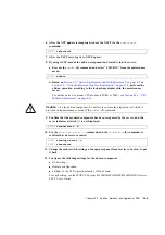
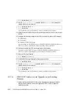
4. Use the
showstatus
(8) command to confirm that a component in Faulted or
Deconfigured status doesn't exist.
If there is no problem, the message of "
No failures found in System
Initialization
" appears. If case of other messages, contact a certified service
engineer before proceeding to the next step.
5. Power off the domain which is assigned with the CMU containing the CPU to be
upgraded.
6. Confirm that the target domain is shut down.
7. Change the mode switch setting on the operator panel from Locked to Service.
8. Collect an XSCF snapshot to archive the system status prior to update.
This data will be of help, in case any problem occurred during the update.
9. Update the XCP version.
For the firmware updating procedures, see the
SPARC Enterprise
M3000/M4000/M5000/M8000/M9000 Servers XSCF User’s Guide
.
10. After the XCP update is completed, reboot the XSCF via the
rebootxscf
command.
11. After the XSCF reset, log in to XSCF again.
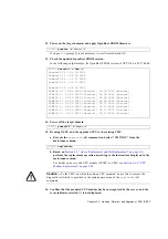
12. Power on the target domain, and apply OpenBoot PROM firmware.
It stops at
ok
prompt. It is not necessary to start Oracle Solaris OS.
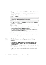
XSCF>
showstatus
XSCF>
poweroff -d
domain_id
XSCF>
showlogs power
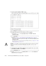
XSCF>
snapshot -t
user@host:directory
XSCF>
rebootxscf
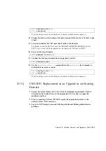
XSCF>
poweron -d
domain_id
Содержание SPARC Enterprise M8000
Страница 4: ......
Страница 15: ...Contents xv Index Index 1 ...
Страница 16: ...xvi SPARC Enterprise M8000 M9000 Servers Service Manual October 2012 ...
Страница 22: ......
Страница 27: ...Chapter 1 Safety and Tools 1 5 M9000 Server Front View ...
Страница 29: ...Chapter 1 Safety and Tools 1 7 Power Supply Unit PSU ...
Страница 37: ...Chapter 1 Safety and Tools 1 15 FIGURE 1 10 M9000 Grounding Port Connection Locations Rear View ...
Страница 38: ...1 16 SPARC Enterprise M8000 M9000 Servers Service Manual October 2012 ...
Страница 54: ...2 16 SPARC Enterprise M8000 M9000 Servers Service Manual October 2012 Removing an I O unit IOU ...
Страница 88: ...2 50 SPARC Enterprise M8000 M9000 Servers Service Manual October 2012 ...
Страница 137: ...Chapter 4 FRU Replacement Preparation 4 43 FIGURE 4 12 Magnified View of Part A M8000 Rear View ...
Страница 145: ...Chapter 4 FRU Replacement Preparation 4 51 FIGURE 4 19 Magnified View of Part B M8000 Rear View ...
Страница 148: ......
Страница 154: ...5 6 SPARC Enterprise M8000 M9000 Servers Service Manual October 2012 ...
Страница 180: ...6 26 SPARC Enterprise M8000 M9000 Servers Service Manual October 2012 FIGURE 6 16 CMU Guide Lock Enlarged ...
Страница 204: ...7 12 SPARC Enterprise M8000 M9000 Servers Service Manual October 2012 FIGURE 7 7 Removing the IOU Rear of M8000 1 1 2 3 ...
Страница 205: ...Chapter 7 I O Unit IOU Replacement 7 13 FIGURE 7 8 Removing the IOU Front of M9000 1 1 2 3 ...
Страница 219: ...Chapter 8 FAN Unit Replacement 8 3 FIGURE 8 2 FAN Mounting Locations Rear of the M8000 FAN_B 2 7 7 5 6 4 3 2 ...
Страница 227: ...Chapter 8 FAN Unit Replacement 8 11 FIGURE 8 9 Removing the FAN Unit Rear of M8000 1 2 ...
Страница 251: ...Chapter 10 Operator Panel Replacement 10 3 FIGURE 10 2 OPNL Mounting Location Front of the M9000 Base Cabinet OPNL ...
Страница 256: ...10 8 SPARC Enterprise M8000 M9000 Servers Service Manual October 2012 ...
Страница 272: ...11 16 SPARC Enterprise M8000 M9000 Servers Service Manual October 2012 ...
Страница 312: ...13 30 SPARC Enterprise M8000 M9000 Servers Service Manual October 2012 ...
Страница 340: ...15 14 SPARC Enterprise M8000 M9000 Servers Service Manual October 2012 ...
Страница 358: ...17 10 SPARC Enterprise M8000 M9000 Servers Service Manual October 2012 ...
Страница 361: ...Chapter 18 AC Section Replacement 18 3 FIGURE 18 2 ACS Mounting Location Front of the M9000 Base Cabinet ACS_B ...
Страница 367: ...Chapter 18 AC Section Replacement 18 9 FIGURE 18 5 Removing the AC Section Front of the M9000 1 2 1 ...
Страница 370: ...18 12 SPARC Enterprise M8000 M9000 Servers Service Manual October 2012 ...
Страница 380: ...19 10 SPARC Enterprise M8000 M9000 Servers Service Manual October 2012 ...
Страница 383: ...Chapter 20 Backplane Replacement 20 3 FIGURE 20 2 BP Mounting Locations Front of the M9000 Base Cabinet BP_B ...
Страница 389: ...Chapter 20 Backplane Replacement 20 9 FIGURE 20 4 Preparation for Accessing BP_A Rear of the M8000 ...
Страница 392: ...20 12 SPARC Enterprise M8000 M9000 Servers Service Manual October 2012 FIGURE 20 6 Removing the BP Rear of the M8000 ...
Страница 409: ...Chapter 20 Backplane Replacement 20 29 FIGURE 20 16 Removing the FANBP Rear of the M8000 ...
Страница 410: ...20 30 SPARC Enterprise M8000 M9000 Servers Service Manual October 2012 FIGURE 20 17 Removing the FANBP Front of M8000 ...
Страница 415: ...Chapter 21 Sensor Unit Replacement 21 3 FIGURE 21 2 SNSU Mounting Location Front of the M9000 Base Cabinet SNSU ...
Страница 422: ...21 10 SPARC Enterprise M8000 M9000 Servers Service Manual October 2012 ...
Страница 425: ...Chapter 22 Media Backplane Replacement 22 3 FIGURE 22 2 MEDBP Mounting Location Front of the M9000 Base Cabinet MEDBP ...
Страница 430: ...22 8 SPARC Enterprise M8000 M9000 Servers Service Manual October 2012 FIGURE 22 4 Removing the MEDBP Front of the M8000 ...
Страница 435: ...Chapter 23 Switch Backplane Replacement 23 3 FIGURE 23 2 SWBP Mounting Location Front of the M9000 Base Cabinet SWBP ...
Страница 439: ...Chapter 23 Switch Backplane Replacement 23 7 FIGURE 23 4 Removing the SWBP Rear of the M8000 ...
Страница 442: ...23 10 SPARC Enterprise M8000 M9000 Servers Service Manual October 2012 ...
Страница 460: ...24 18 SPARC Enterprise M8000 M9000 Servers Service Manual October 2012 ...
Страница 484: ...25 24 SPARC Enterprise M8000 M9000 Servers Service Manual October 2012 ...
Страница 494: ...A 10 SPARC Enterprise M8000 M9000 Servers Service Manual October 2012 ...
Страница 537: ...Appendix B Components B 43 FIGURE B 38 FAN Backplane FANBP_B FIGURE B 39 FAN Backplane FANBP_C ...
Страница 544: ...C 4 SPARC Enterprise M8000 M9000 Servers Service Manual October 2012 ...
Страница 552: ...D 8 SPARC Enterprise M8000 M9000 Servers Service Manual October 2012 ...


