background image

System expansions

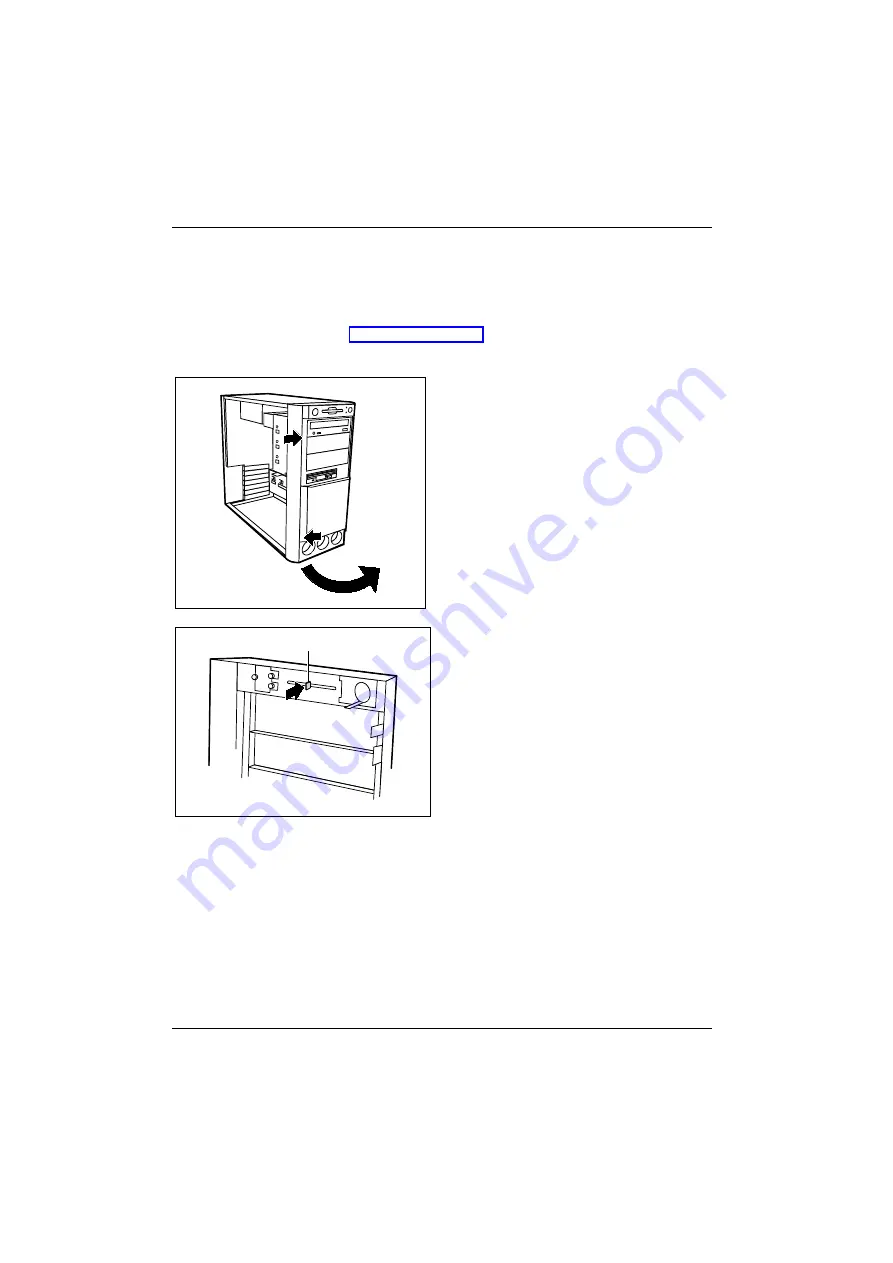
Installing and removing SmartCard reader

48 - English

A26361-K547-Z400-1-7419

Installing and removing SmartCard reader

You can only install a SmartCard reader when there is a corresponding slot in the front of the
casing.

Ê


Open the workstation (see "Opening the workstation").

Installing a SmartCard reader for the first time

1

2

3

Ê


Remove the front cover: Press the two
retaining lugs in the direction of the
arrows (1 + 2).

Ê


Swivel the front cover in the direction of
the arrow (3).

a

The SmartCard slot on the rear of the front
panel is protected by a plastic tag (a) when
the device is shipped.

Ê


Break off the plastic (a) tag.

Ê


Reattach the front cover. Hang the front cover on the right side and turn it to close. Both snap
hooks must be engaged.

Содержание Siemens CELSIUS 4 Series

Страница 1: ...CELSIUS Betriebsanleitung Operating Manual CELSIUS 4xx ...

Страница 2: ...tie und Ergonomie Aktuelle Informationen zu unseren Produkten Tipps Updates usw finden Sie im Internet http www fujitsu siemens com Do you have any questions If you have any technical questions please refer to your sales partner your sales outlet You will find further information in the Safety Warranty and Ergonomics booklet The latest information on our products tips updates etc can be found on t...

Страница 3: ......

Страница 4: ...ciclado Questo manuale è stato stampato su carta da riciclaggio Denna handbok är tryckt på recyclingpapper Dit handboek werd op recycling papier gedrukt Herausgegeben von Published by Fujitsu Siemens Computers GmbH Bestell Nr Order No A26361 K547 Z400 4 7419 Printed in the Federal Republic of Germany AG 0302 03 02 A26361 K547 Z400 1 7419 CELSIUS 4xx BETRIEBSANLEITUNG OPERATING MANUAL ...

Страница 5: ...CELSIUS 4xx Operating Manual Introduction Important notes Preparation for use and operation Troubleshooting and tips System expansions Technical data Index March 2002 edition ...

Страница 6: ...arks of their respective owners whose protected rights are acknowledged All rights including rights of translation reproduction by printing copying or similar methods in part or in whole are reserved Offenders will be liable for damages All rights including rights created by patent grant or registration of a utility model or design are reserved Delivery subject to availability Right of technical m...

Страница 7: ...kstation 14 Switching the workstation on and off 15 Switching on the workstation for the first time 16 Switching the workstation on 17 Switching off the workstation 17 Indicators on the workstation 18 Keyboard 19 Important keys and key combinations 20 Working with floppy disks 21 Settings in BIOS Setup 22 Property and data protection 22 Locking the workstation mechanically 22 Access authorisation ...

Страница 8: ...e drive 39 Removing an accessible drive 41 Changing the floppy disk drive 42 Installing and removing hard disk drives 43 Removing the drive cage 44 Installing the drive cage 46 Installing a hard disk drive in a 5 1 4 inch drive bay 47 Installing and removing SmartCard reader 48 Extensions to the system board 51 Upgrading main memory 51 Replacing processor 51 Replacing the lithium battery 51 Techni...

Страница 9: ...means of passwords In addition you can also lock your workstation mechanically using the casing lock Additional information on this workstation is also contained in in the Safety Warranty and Ergonomics booklet in the manual First Steps Windows NT 4 0 Setup in the operating manual for the monitor in the Technical Manual for the system board in the BIOS Setup manual in the information files e g TXT...

Страница 10: ......

Страница 11: ...ains voltage To completely disconnect the mains voltage remove the power plug from the grounded mains outlet Replace the lithium battery on the system board in accordance with the instructions in the System expansions Replacing the lithium battery chapter Caution components in the system can get very hot Keep this operating manual together with your device If you pass on the device to third partie...

Страница 12: ... GmbH Recyclingcenter D 33106 Paderborn Tel 49 0 5251 818 010 Fax 49 0 5251 818 015 CE marking The shipped version of this device complies with the requirements of the EEC directives 89 336 EEC Electromagnetic compatibility and 73 23 EEC Low voltage directive FCC Class B Compliance Statement The following statement applies to the products covered in this manual unless otherwise specified herein Th...

Страница 13: ...l transportation manoeuvres are completed Never drop the monitor risk of implosion Cleaning the workstation Turn off all power and equipment switches and pull the power plug out of the grounded mains outlets The inside of the workstation casing may only be cleaned by authorised specially trained personnel Do not use any cleaning agents that contain abrasives or may corrode plastic Ensure that no l...

Страница 14: ......

Страница 15: ...cal sales outlet immediately i If you have received drives or boards with your Workstation please do not install them until after initial installation How to install drives and boards is described in the chapter System expansions Steps for initial setup When starting up for the first time the devices monitor mouse keyboard etc are connected to the workstation and the software provided is set up Wh...

Страница 16: ...over the ventilation areas of the monitor and the workstation Do not place several workstations one above the other Connecting devices The power plug must be disconnected Read the documentation on the external device before connecting it Do not connect or disconnect cables during a thunderstorm Always take hold of the actual plug Never unplug a cable by pulling the cable itself Connect and disconn...

Страница 17: ... similar Exact details of the position of the ports are supplied in the Technical Manuals for the boards Keyboard port purple 1 Serial interface 1 turquoise PS 2 mouse port green 2 Serial interface 2 turquoise Monitor port blue Parallel interface Printer burgundy USB port black Game port gold Microphone jack mono pink SmartCard reader Audio output Line out lime green LAN LAN connector Audio input ...

Страница 18: ...e mouse Ê Plug the connector of the mouse cable into the mouse port i If you do not attach a mouse at the PS 2 mouse port you can disable the mouse controller in the BIOS Setup in order to free the IRQ12 for a different application Connecting devices with a serial or a parallel connection Ê Connect the data cable to the external device Ê Connect the data cable of the external device to the appropr...

Страница 19: ...e of the monitor into the monitor port of the workstation 1 1 2 Ê Depending on the connector plug the monitor power cable into either the workstation 1 or the grounded mains outlet 2 You may only plug the monitor power cable into the monitor connector of the workstation if the rated current of the monitor is less than 1 5 A 230 V or 3 A 115 V The rated current for the monitor is given on the monit...

Страница 20: ...your workstation displays a manual voltage adjuster ensure that the displayed rated voltage correctly matches the local rated voltage 100 V 127 V 200 V 240 V 100 V 127 V 200 V 240 V 1 1 1 1 1 Notch for inserting the screwdriver Ê Check the voltage setting The value indicated with an arrow must be compatible with the local rated voltage 115 100 V to 127 V 230 200 V to 240 V If the voltage setting i...

Страница 21: ...he workstation to the mains voltage Preparation for use and operation A26361 K547 Z400 1 7419 English 13 1 2 1 2 Ê Plug the workstation s power cable into the workstation 1 and then into the grounded mains outlet 2 ...

Страница 22: ...h the casing lock you can mechanically lock the workstation and with the drive cover you can block access to the drives Unlocking the workstation 1 2 Ê Turn the key anticlockwise 1 Ê Slide the drive cover in direction of the arrow 2 Locking the workstation 1 2 Ê Slide the drive cover in direction of the arrow 1 and turn the key clockwise 2 ...

Страница 23: ...dicator 3 is not lit and the power button 2 is disabled Workstation is ready for operation The main switch 1 is in position I In this mode you can switch the workstation on with the ON OFF switch 2 The ready to operate status corresponds to the stand by status of a TV set A full description of the power on indicator 3 can be found in the Indicators on the workstation section Workstation is on The ...

Страница 24: ...This number is located on a sticker on your workstation Ê Switch your monitor on Ê Switch the workstation on with the main switch at the rear of the workstation The main switch 1 is in position I Ê Switch the workstation on with the ON OFF switch The power on indicator lights green and the workstation is started Ê Adjust the brightness if necessary see the operating manual for the monitor Some var...

Страница 25: ...uested to do so If the workstation is ready to operate the workstation consumes a minimum of energy and can be switched on by an external device provided that the remote on functionality is set to Enabled in the BIOS Setup If you use the main switch to switch off the workstation it uses no power i The main switch and the ON OFF switch do not disconnect the workstation from the mains voltage To com...

Страница 26: ... drive of the workstation is accessed You may only remove the floppy disk when the indicator is unlit 2 CD ROM indicator The indicator lights up when the CD ROM drive of the workstation is accessed You may only remove the CD when the indicator is dark 3 SmartCard reader indicator The indicator lights up when the SmartCard reader is accessed You may only remove the SmartCard when the indicator is u...

Страница 27: ...rgy saving mode the workstation must not be switched off with the main power switch if present or disconnected from the mains as this may result in data loss The indicator does not light up The workstation is switched off power switch at 0 or disconnected from the power supply or ready to operate If the workstation is ready to operate the workstation can be enabled with the ON OFF switch Keyboard ...

Страница 28: ...he Windows Start menu Menu key invokes the menu for the marked item Windows Shift key enables upper case letters and the upper key symbols to be used Alt Gr Alt Gr e g German keyboard produces a character shown on the right hand side of a key e g the character on the key ß E Euro key outputs the Euro symbol when pressed simultaneously with the Alt Gr key Num Lock Num Lock key by pressing the Num L...

Страница 29: ...floppy disk 4 Identification of a 1 44 MB floppy disk or write protect switch on a 120 MB floppy disk 5 Eject button for inserted floppy disks 6 Disk is write protected 7 Disk is not write protected To insert a diskette Ê Push the floppy disk into the drive in the insertion direction 1 until it engages The label should be facing upward To remove a diskette Ê Push the eject button 5 Protect the flo...

Страница 30: ...anical lock on your workstation enable you to protect your system and personal data in a number of ways against unauthorised access By combining these options you can achieve maximum protection for your system Locking the workstation mechanically With the casing lock you can mechanically lock the workstation and with the drive cover you can block access to the drives Access authorisation via Smart...

Страница 31: ...offers you various options for protecting your personal data against unauthorised access e g Preventing unauthorised BIOS Setup entry Preventing unauthorised system access Preventing unauthorised access to the settings of boards with their own BIOS Preventing system booting from the diskette drive Activating virus warnings Preventing unauthorised writing of diskettes Protecting BIOS from being ove...

Страница 32: ...ystemLock controls access to your PC When a SmartCard is initialised permissions are assigned for system access system setup system setup admin You can configure several SmartCards for one system and initialise them with different permissions In this way users can be divided into user groups Users of a user group use SmartCards with the same permissions Additional instructions for PC Lock SystemLo...

Страница 33: ...The system starts following entry of the user PIN You can change the user PIN an the administrator PIN unlock locked SmartCards open and change the BIOS Setup and generate additional SmartCards for this system For instructions on how to install and operate PC Lock or SystemLock and how to initialise SmartCards see the BIOS Setup manual Operating the SmartCard reader Operating the internal SmartCar...

Страница 34: ......

Страница 35: ...ontact your sales outlet or our customer service centre Installing new software When installing programmes or drivers important files may be overwritten and modified To be able to access the original data in the case of any problems following installation you should backup your hard disk prior to installation Power on indicator remains unlit after you have switched on your device This may be due t...

Страница 36: ...t connected Ê Switch off the monitor and the workstation Ê Check that the power cable is properly connected to the monitor and workstation or to the grounded mains outlet Ê Check that the monitor cable is properly connected to the workstation and monitor if not permanently attached Ê Switch on the monitor and the workstation Wrong monitor has been set under Windows NT Ê Restart the workstation in ...

Страница 37: ...otection of the floppy disk or the floppy disk drive is activated refer also to the Technical Manual for the system board or to the BIOS Setup manual Ê Check the relevant entries for Diskette A or B in the Main menu of the BIOS Setup Ê Check that the floppy disk drive controller is enabled refer also to the Technical Manual for the system board or in the manual BIOS Setup Ê Check that the cables o...

Страница 38: ... you should close applications you do not require or call the applications in a different order BIOS settings in power management do not become active The Auto insert notification setting may be active for the CD ROM drive This setting causes Windows 9x to inquire about any modifications on the drive at regular intervals Because of this the timer for the idle time cannot time out To activate power...

Страница 39: ...at the maximum permissible temperatures of the individual components are not exceeded This chapter describes all the activities required to modify your workstation hardware e g installing boards or drives Memory and processor upgrading are described in the Technical Manual for the system board Read the supplied documentation before installing new drives and or boards Refer to the Technical Manual ...

Страница 40: ...ull the power plug out of the mains outlet Ê If any cables attached to the workstation are obstructing you pull out the connectors on the workstation Ê Place the workstation in a convenient working position 1 4 a 3 2 2 Ê Unlock the system unit 1 Ê Loosen the screws 2 Ê Push the side cover in the direction of the arrow 3 until the distance a is approximately 10 mm Ê Lift the side cover out of the c...

Страница 41: ... the arrow 2 until it engages Ê Fasten the screws 3 Ê Lock the system unit 4 Ê Return the system unit to its original position Ê Reconnect the disconnected cables Installing and removing a board Observe the notes on installing and removing boards in the chapter Important notes The number position and arrangement of the board slots on the system board can be found in the Technical Manual for the sy...

Страница 42: ... Ê Make the required settings for the board Ê Push the board up to its slot 4 Ensure that the end of a long board without angle bracket fits into the corresponding guide of the workstation Ensure also that the point of the angle bracket slots into guide a Ê Press the board into the slot so that it engages Ê Replace the clip 5 which fixes the board Make sure that the clip engages when released Ê If...

Страница 43: ...ons you must refit the cover plate if you remove the board Ê Take the new board out of its packaging Ê Make the required settings for the board Ê Push the board up to its slot 3 With long boards please observe The side of the board without a metal angle bracket must lie in the corresponding guide of the casing The point of the angle bracket must engage in the guide Ê Press the board into the slot ...

Страница 44: ...2 Ê Remove the board from the workstation 3 Ê Place the board into appropriate packaging For cooling protection against fire and in order to comply with EMC electromagnetic compatibility regulations you must refit the cover plate Ê Push the rear slot cover plate into the slot 4 Ensure that the end of the cover engages into the guide a Ê Replace the clip 5 which fixes the board Make sure that the c...

Страница 45: ...into appropriate packaging For cooling protection against fire and in order to comply with EMC electromagnetic compatibility regulations you must refit the cover plate Ê Push the rear slot cover plate into the slot 3 Ê Fasten the screw 4 Ê Close the system unit see Closing the Workstation i If you have installed or removed a PCI board please check the relevant PCI slot settings in the BIOS Setup I...

Страница 46: ...e Technical Manual for the system board SCSI drives If you want to install a SCSI drive you require a SCSI controller and a SCSI cable Note that Not every SCSI controller is suitable for operating SCSI hard disks Each SCSI device must be assigned its own SCSI ID The SCSI cable must always be terminated at the end either with a drive with an activated termination or with a terminating resistor moun...

Страница 47: ...g an accessible drive Ê Open the workstation see Opening the workstation A B 1 2 Ê Pry the plastic drive cover A out of the front cover Ê Pry the shielding plate B on left hand side out of the bay Do not throw away the safety covers If you remove the drive again later you will have to reinstall the covers ...

Страница 48: ...the drive settings if necessary to the settings of installed drives as well 3 1 2 Ê Slide the drive into the workstation 1 Ê Plug the connectors of the data cable and the power supply cable into the drive 2 Ê Fasten the drive with the screws 3 Ê Close the system unit see Closing the Workstation i It may be necessary to modify the entry for the drive in the BIOS Setup ...

Страница 49: ...supply connectors from the desired drive 1 Ê Remove the screws 2 and take the drive out of the workstation 3 A B Ê Insert the shielding plate B on the right hand side on the installation bay and press it in Ê Press the plastic drive cover A into the front panel until it snaps into place Ê Close the system unit see Closing the Workstation i It may be necessary to modify the entry for the drive in t...

Страница 50: ...s from the floppy disk drive 1 Ê Remove the screw 2 Ê Take the drive out of the workstation 3 Ê Take the new floppy disk drive out of its packaging 3 2 Ê Slide the drive into the workstation 1 Ê Plug the data and the power supply connectors into the floppy disk drive 2 Ê Fasten the drive with the screw 3 Ê Close the system unit see Closing the Workstation i It may be necessary to modify the entry ...

Страница 51: ... port 1 and accessible drives for example CD ROMs to IDE port 2 see also the Technical Manual for the system board SCSI drives If you want to install a SCSI drive you require a SCSI controller and a SCSI cable Note that Not every SCSI controller is suitable for operating SCSI hard disks Each SCSI device must be assigned its own SCSI ID The SCSI cable must always be terminated at the end either wit...

Страница 52: ...1 The temperature sensor is attached to the drive cage During the installation you will have to attach the temperature sensor again Ê Pull the drive cage out of the casing in the direction of the arrow 2 Installing a hard disk drive Ê Take the new hard disk drive out of its packaging Ê Make the required settings e g master slave settings on the drive 2 2 2 1 2 Ê Slide the hard disk drive into the ...

Страница 53: ...nstalling and removing hard disk drives System expansions A26361 K547 Z400 1 7419 English 45 Removing a hard disk drive 1 1 1 1 2 Ê Loosen the screws 1 Ê Pull the hard disk drive out of the drive cage 2 ...

Страница 54: ...he guide slots Ê Secure the drive cage with the screw 2 Ê Before tightening the screw 2 into place please take care to attach the temperature sensor as well Ê Connect the data and power supply cables to the hard disk drive or to the hard disk drives i Connect the blue plug of the data cable to the connection on the system board Connect the plug on the other end to the hard disk drive Ê Close the w...

Страница 55: ...come in various sizes The installation frame or angled installation bracket must have the height of a 5 1 4 inch bay The illustrated installation frame is an example and may differ from the model installed in your workstation 1 1 Ê Fasten the drive with the four screws 1 Ê Install the installation frame with the drive in the desired front bay see Installing an accessible drive Ê Close the slot wit...

Страница 56: ...he workstation Installing a SmartCard reader for the first time 1 2 3 Ê Remove the front cover Press the two retaining lugs in the direction of the arrows 1 2 Ê Swivel the front cover in the direction of the arrow 3 a The SmartCard slot on the rear of the front panel is protected by a plastic tag a when the device is shipped Ê Break off the plastic a tag Ê Reattach the front cover Hang the front c...

Страница 57: ...onnector for the SmartCard reader on the system board see the Technical Manual for the system board Ê Install the carrier for the SmartCard reader in the casing see Installing the carrier Replacing the SmartCard reader Removing the bracket 2 1 Ê Remove the screw 1 Ê Pull the SmartCard reader carrier out of the PC casing 2 i If the carrier cannot be pulled out of the casing because the power supply...

Страница 58: ...nt side facing upwards 1 Ê Secure the SmartCard reader with the screw 2 Ê Attach the cable to the SmartCard reader 3 and to the connector for the SmartCard reader on the system board see the Technical Manual for the system board Installing the carrier 2 1 Ê Place the carrier on the guide clips in the casing Ê Slide the carrier in the direction of the arrow as far as it will go 1 Ê Fasten the carri...

Страница 59: ...e desired changes see the Technical Manual for the system board Replacing the lithium battery In order to permanently save the system information a lithium battery is installed to provide the CMOS memory with a current A corresponding error message notifies the user when the charge is too low or the battery is empty The lithium battery must then be replaced Incorrect replacement of the lithium bat...

Страница 60: ...ensions to the system board 52 English A26361 K547 Z400 1 7419 1 2 3 Ê Lift the contact 1 a few millimetres and remove the lithium battery from its socket 2 Ê Insert a new lithium battery of the same type into the socket 3 ...

Страница 61: ...V 127 V 200 V 240 V 7 0 A 3 5 A 3 0 A 1 5 A 8 0 A 4 0 A 3 0 A 1 5 A Typical power draw in operation CELSIUS 4xx 60 W Dimensions Width depth height Typical Weight CELSIUS 4xx 205 mm 500 mm 443 mm ca 14 kg 137 54 N in basic configuration Environmental conditions Environment class 3K2 Environment class 2K2 DIN IEC 721 part 3 3 DIN IEC 721 part 3 2 Temperature Operation 3K2 Transport 2K2 15 C 35 C 25 ...

Страница 62: ......

Страница 63: ...etup 22 Contents of delivery 7 Control key 20 Ctrl key 20 Ctrl Alt Del 20 Cursor control keys 19 D Data protection 22 Date not correct 29 Devices connecting 8 ports 9 Disposal 4 Drive installing 39 removing 40 Drive cage 43 installing 45 removing 43 Drive cover 14 E Electromagnetic compatibility 4 Energy saving 4 Enter key 20 Ergonomic video workstation 8 Error date 29 floppy disk 29 mouse 29 scre...

Страница 64: ...Memory upgrading 50 Menu key 20 Message indicator 18 Microphone jack 9 Monitor cleaning 5 connecting 11 remains blank 28 transporting 4 Monitor port 9 Mouse cleaning 5 connecting 10 error 29 Mouse port 9 N New installation software 27 No picture 28 Not enough memory 30 Notational conventions 1 Note boards 3 CE certificate 4 disposal 4 energy saving 4 important 3 manufacturer 4 safety 3 Num Lock ke...

Страница 65: ...7 Standard keyboard connecting 10 Start key 20 Streamer installing 39 removing 40 Summer time 29 System board siehe Systembaugruppe extensions 50 System expansion 31 System settings BIOS Setup 22 System unit siehe Workstation T Task Manager 20 Time not correct 29 Time daylight savings 29 Tips 27 30 Transport 4 Trouble floppy disk 29 mouse 29 screen 28 workstation 27 Troubleshooting 27 U Unpacking ...

Отзывы: