


46
Operating Manual
RX220
Operating and Indicator Elements
Preparation for Use and Operation
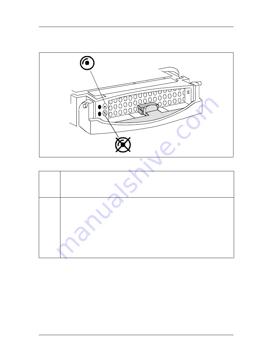
Hard disk drive control indicators
Figure 10: HDD module: indicators
LED
green
HDD access
–
lights: HDD in active phase
–
does not light: HDD inactive
LED
amber
HDD FAULT (in conjunction with a RAID controller)
–
does not light: No HDD Error
–
lights: HDD Faulty or Rebuild Stopped (drive defective/needs
replacing, a rebuild process was stopped or the HDD module is
not correctly inserted)
–
slow blink: HDD Rebuild (the data is restored by the RAID
controller after changing a hard disk drive)
–
fast blink: HDD Identify
HDD Access
HDD Fault
Содержание PRIMERGY RX220
Страница 42: ......
Страница 54: ......
Страница 56: ......
Страница 62: ......
Страница 74: ...74 Operating Manual RX220 Abbreviations ZCR Zero Channel RAID ...
Страница 82: ......
Страница 84: ... cognitas Gesellschft für Technik Dokumentation mbH 2005 Pfad U RX220 rx220_ba rx220_e pdf rx220us nac ...
Страница 86: ......