En-23
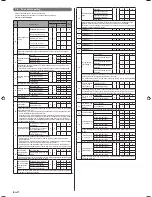
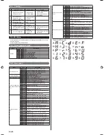
Checklist
9. 3.
Check description
Check method
Criteria
1
High and low pressure
values are normal.
Check it with a
pressure gauge.
Cooling: low pressure ap-
prox. 0.8 MPa
Heating: high pressure ap-
prox. 3.0 MPa
2
Drain water is dis-
charged smoothly
through the drain hose.
Check it by pour-
ing water.
―
3
Indoor and outdoor unit
fans are operating.
Check them visu-
ally.
―
4
Compressor operates after
the indoor unit operates.
Check the operat-
ing sound.
―
5
Difference between inlet
and outlet temperatures
is normal.
Measure the inlet
and outlet temper-
atures.
Temperature difference 10
degrees
6
Error is not displayed
Check the 7
segment LED
indicator
Error blinking or no error
code display
LED Status
10.
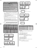
You can determine the operating status by the lighting up and blinking of the 7 seg-
ment LED indicator.
Check the status using the table below.
Normal operation mode
10. 1.
Mode
Code
Description
Operation
C L
Cooling
H
t
Heating
o
r During oil recovery operation
d F During defrosting operation
P C During peak cut operation
L n During low noise operation
S n During setting of snowfall mode
Error codes
10. 2.
Mode
Code
Description
Communication error
E 1 3. 1 Communication error between outdoor units
E 1 4. 1 Outdoor unit network communication 1 error
E 1 4. 2 Outdoor unit network communication 2 error
E 1 4. 5 The number of indoor unit shortage
Function setting error
E 2 8. 1 Auto address setting error
E 2 8. 4 Signal ampli
fi
er auto address error
Indoor unit actuator error E 5 U. 1 Indoor unit miscellaneous error
Outdoor unit PCB/Elec-
trical component/ Switch
error
E 6 1. 5 Outdoor unit reverse/missing phase & wiring error
E 6 2. 3 Outdoor unit EEPROM access error
E 6 2. 6 Outdoor unit inverters communication error
E 6 2. 8 Outdoor unit EEPROM data corruption error
E 6 3. 1 Outdoor unit inverter error
E 6 7. 2
Outdoor unit inverter PCB power short interruption
error
E 6 8. 1 Outdoor unit magnetic relay error
E 6 8. 2
Outdoor unit rush current limiting resister temp. rise
error (protective operation)
E 6 9. 1
Outdoor unit transmission PCB parallel
communication error
Outdoor unit sensor
error
E 7 1. 1 Outdoor unit discharge temp. thermistor 1 error
E 7 1. 2 Outdoor unit discharge temp. thermistor 2 error
E 7 2. 1 Outdoor unit compressor temp. thermistor 1 error
E 7 2. 2 Outdoor unit compressor temp. thermistor 2 error
E 7 3. 3 Outdoor unit heat ex. liquid temp. thermistor error
E 7 4. 1 Outside air temp. thermistor error
E 7 5. 1 Outdoor unit suction gas temp. thermistor error
E 7 7. 1 Outdoor unit heat sink temp. thermistor error
E 8 2. 1
Outdoor unit sub-cool heat ex. gas inlet temp. therm-
istor error
E 8 2. 2
Outdoor unit sub-cool heat ex. gas outlet temp.
thermistor error
E 8 3. 1 Outdoor unit liquid pipe temp. thermistor 1 error
E 8 3. 2 Outdoor unit liquid pipe temp. thermistor 2 error
E 8 4. 1 Outdoor unit current sensor 1 error (permanent stop)
E 8 6. 1 Outdoor unit discharge pressure sensor error
E 8 6. 3 Outdoor unit suction pressure sensor error
E 8 6. 4 Outdoor unit high pressure switch 1 error
E 8 6. 5 Outdoor unit high pressure switch 2 error
Outdoor unit actuator
error
E 9 2. 1 Outdoor unit compressor 2 error
E 9 2. 2 Outdoor unit compressor 2 current value error
E 9 3. 1 Outdoor unit inverter compressor start up error
E 9 4. 1 Outdoor unit trip detection
E 9 5. 5 Outdoor unit compressor motor loss of synchronization
E 9 7. 1 Outdoor unit fan motor 1 lock error
E 9 7. 4 Outdoor unit fan motor 1 undervoltage error
E 9 7. 5
Outdoor unit fan motor 1 temperature error (protective
action)
E 9 U. 2 Outdoor slave unit error
Refrigerant system error
E A 1. 1
Outdoor unit discharge temperature 1 error (perma-
nent stop)
E A 2. 1
Outdoor unit discharge temperature 2 error (perma-
nent stop)
E A 3. 1 Outdoor unit compressor 1 temperature error
E A 3. 2 Outdoor unit compressor 2 temperature error
E A 4. 1 Outdoor unit high pressure error
E A 4. 2 Outdoor unit high pressure protective action 1
E A 4. 3 Outdoor unit high pressure protective action 2
E A 5. 1 Outdoor unit low pressure error
E A C. 4 Outdoor unit heat sink temperature error
㪃
㪃
㪃
㪃
㪃
㪃
㪃
㪃
㪣㪑
㪟㪑
㪡㪑
㪃
㪍㪑
㪃
㪃
㪃
㫅㪑
㫆㪑
㫉㪑
㫋㪑
㪃
㪃
㪃
㪃
㪬㪑
㪃
㪐㪑
㪏㪑
㪃
㪃
㪃
㪃
㪧㪑
㪻㪑
㪪㪑
㪘㪑
㪝㪑
㪚㪑
㪜㪑
㪇㪑
㪌㪑
㪃
㪃
㪃
㪃
㪃
㪊㪑
㪈㪑
㪉㪑
㪃
㪎㪑
㪋㪑
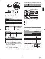
7 segment LED indicator:
9378945104-01_IM.indb Sec1:23
9378945104-01_IM.indb Sec1:23
2013-3-12 14:08:31
2013-3-12 14:08:31

