background image

En-17

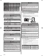
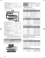
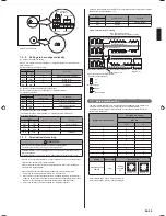
Push button setting

7. 4. 

Various functions can be set when necessary.
Perform settings after all indoor units have stopped operation.

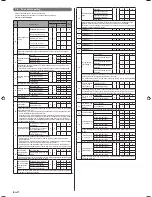
A: List of Settings

Table. 

No

Setting Item

7 segment LED indicator

Factory 

setting

First 2 

digits

Last 2 digits

00

Pipe length set-

ting *1

Standard (40 to 65 m)

0

0

0

0

Short (less than 40 m)

0

1

Medium (65 to 90 m)

0

2

Long 1 (90 to 120 m)

0

3

Long 2 (120 to 150 m)

0

4

Pipe length means the length between master outdoor unit and the nearest 

indoor unit.

10

Sequential start 

shift *1

Normal

1

0

0

0

21 sec. Delay

0

1

42 sec. Delay

0

2

63 sec. Delay

0

3

The start-up timing of outdoor unit (compressor) can be set up so that it can 

delay several seconds.

This feature is useful when multiple number of outdoor units are installed and 

turned on at the same time to limit the starting current.

11

Cooling capacity 
shift *1

Normal mode

1

1

0

0

Save energy mode

0

1

High power mode 1

0

2

High power mode 2

0

3

(Forbidden)

0

4

Set this item when necessary.

12

Heating capacity 
shift *1

Normal mode

1

2

0

0

Save energy mode

0

1

High power mode 1

0

2

High power mode 2

0

3

Set this item when necessary.

13

(Forbidden)

1

3

0

0

20

Switching between 
batch stop or 
emergency stop *1

Batch stop

2

0

0

0

Emergency stop

0

1

This mode selects the pattern of the stop function to be operated by the external 

input terminal (CN134).

•  Batch stop: The stop of all indoor units connected to same refrigerant system 

due to input signal coming from CN134.

•  Emergency stop: When emergency stop is actuated, the indoor unit does not 

accept the operation command from the remote controller. On the other hand, 

when the emergency stop is released (no input from CN134), the air condi-

tioner does not return to the original operation until the indoor unit is turned on 

by the remote controller.

21

Operation mode 
selecting method 
*1

Priority given to the 

fi

 rst 

command

2

1

0

0

Priority given to external 
input of outdoor unit

0

1

Priority given to adminis-
trative indoor unit

0

2

Select the priority setting of the operation mode.

•  Priority given to the 

fi

 rst command: Priority is given to the operation mode 

which is set 

fi

 rst.

•  Priority given to external input of outdoor unit: Priority is given to the operation 

mode which is set by the external input terminal (CN132).

•  Priority given to administrative indoor unit: Priority is given to the operation 

mode of the administrative indoor unit which is set by the wired remote control-

ler.

22

Snow falling 
protection fan 
mode *1

Normal mode

2

2

0

0

Snow falling protection fan 
mode

0

1

This mode operates the fans of outdoor units in order to prevent the units from stop-
ping operation when they are covered by snow.

23

Interval setting 
for snow falling 
protection fan 
mode *1

Standard (30 minutes)

2

3

0

0

Short 1 (5 minutes)

0

1

Short 2 (10 minutes)

0

2

Short 3 (20 minutes)

0

3

When the snow falling protection fan mode is set, the operation interval of the fans 

of outdoor units can be selected.

24

High static pressure 
mode

Standard

2

4

0

0

High static pressure 1 
(equivalent to 30Pa)

0

1

High static pressure 2 
(equivalent to 80Pa)

0

2

(Forbidden)

0

3

When installing a duct to the blow-off outlet of an outdoor unit, set the high static 

pressure mode according to the static pressure of the duct to be installed.

Furthermore, use this setting if the air blow of an outdoor unit is poor, such as when 

installed in a place with a low ceiling.

25

(Forbidden)

2

5

0

0

26

(Forbidden)

2

6

0

0

27

(Forbidden)

2

7

0

0

28

(Forbidden)

2

8

0

0

29

(Forbidden)

2

9

0

0

30

Energy saving 
level setting *1

Level 1 (stop)

3

0

0

0

Level 2 (operated at 40% 
capacity)

0

1

Level 3 (operated at 60% 
capacity)

0

2

Level 4 (operated at 80% 
capacity)

0

3

Level 5 (operated at 100% 
capacity)

0

4

The capacity limit can be selected by the external input terminal (CN133) when 
operating with the “Energy Saving Peak Cut function”.
The lower the level, the more the effect of energy saving, but the cooling/heating 
performance will also drop.

40

Capacity priority 
setting (in low 
noise mode) *1

Off (quiet priority)

4

0

0

0

On (capacity priority)

0

1

If the cooling/heating performance becomes insuf

fi

 cient when the low noise mode is set, 

it is possible to set “capacity priority” that automatically cancels the low noise mode (once 
performance is restored, the mode will automatically return to the low noise mode).

41

Low noise mode 
setting *1

Off (Normal)

4

1

0

0

On (Low noise mode)

0

1

42

Low noise mode 
operation level 
setting *1

Level 1 (55 dB)

4

2

0

0

Level 2 (50 dB)

0

1

The noise level when operating in the low noise mode can be set.

60

Back up operation 1 
*1

On

6

0

0

0

Off

0

1

70

Electricity meter 
No. setting 1 *2

Setting number (x00)

7

0

0

0

Setting number (x01)

0

1

······

···

···

Setting number (x98)

9

8

Setting number (x99)

9

9

Set the ones digit and tens digit of the No. of the electricity meter connected to 
CN135.

71

Electricity meter 
No. setting 2 *2

Setting number (0xx)

7

1

0

0

Setting number (1xx)

0

1

Setting number (2xx)

0

2

Set the hundreds digit of the No. of the electricity meter connected to CN135.

72

Electricity meter 
pulse setting 1 *3

Setting number (xx00)

7

2

0

0

Setting number (xx01)

0

1

······

···

···

Setting number (xx98)

9

8

Setting number (xx99)

9

9

Set the ones digit and tens digit of the No. of the electricity meter pulse setting 
connected to CN135.

9378945104-01_IM.indb   Sec1:17

9378945104-01_IM.indb   Sec1:17

2013-3-12   14:08:27

2013-3-12   14:08:27

Содержание Airstage AJH108LALH

Страница 1: ...or authorized service personnel only INSTALLATIONSANLEITUNG Nur für autorisiertes Fachpersonal MANUEL D INSTALLATION MANUAL DE INSTALACIÓN Pour le personnel agréé uniquement Únicamente para personal de servicio autorizado MANUALE DI INSTALLAZIONE A uso esclusivo del personale tecnico autorizzato ΕΓΧΕΙΡΙΔΙΟ ΕΓΚΑΤΑΣΤΑΣΗΣ Μόνο για εξουσιοδοτημένο τεχνικό προσωπικό MANUAL DE INSTALAÇÃO Apenas para téc...

Страница 2: ...s exposed to fire it will create a hazardous gas Electrical work must be performed in accordance with this Installation manual by a person certified under the national or regional regulations Be sure to use a dedi cated circuit for the unit An insufficient power supply circuit or improperly performed electrical work can cause serious accidents such as electric shock or fire For wiring use the pres...

Страница 3: ...tion Especially when replacing a conventional refrigerant other than R410A model with a new refrigerant R410A model always replace the conventional piping and flare nuts with the R410A piping and flare nuts Models that use refrigerant R410A have a different charging port thread diameter to prevent erroneous charging with R22 R407C and for safety Therefore check beforehand The charging port thread ...

Страница 4: ... of the leakage of flammable gas in the vicinity Install the unit in an area that is away from the exhaust or vent ports that discharge vapor soot dust or debris Install the indoor unit outdoor unit power supply cable transmission cable and remote control cable at least 1 meter away from a television or radio The purpose of this is to prevent TV reception interference or radio noise Even if they a...

Страница 5: ...5 2 mm 4 Fig J J Side view Front Rear Wall Wall 5 Fig L5 L5 500 h5 500 h5 H5 H5 Front view Wall Wall 6 Fig Top view 800mm or more 800mm or more 20mm or more 20mm or more L4 L3 L5 L5 7 Fig Top view 500mm or more 1000mm or more 20mm or more 20mm or more L4 L3 L5 L5 When install near unlimited height wall 3 3 2 Single and multiple installations 1 There are no restrictions on the height of the wall Th...

Страница 6: ...re is the air flow resistance that includes 1 the discharge duct resistance the other additional resistance like discharge grill and so on Refer to the section on Push Switch Setting in Chapter 7 Field Setting 2 Transportation the outdoor unit 3 4 Product mass kg AJ A72LALH 220 AJ A90LALH 220 AJ 108LALH 275 AJ 126LALH 303 AJ 144LALH 303 Hoisting method When hanging the outdoor unit and conveying i...

Страница 7: ...ation 4 1 CAUTION When connecting multiple outdoor units set the nearest outdoor unit to the indoor unit on the refrigerant pipe as the master unit When connecting multiple outdoor units install the outdoor unit with the largest nominal system capacity nearest to the indoor unit on the refrigerant pipe fol lowed by those with less nominal system capacities Capacity Master Slave Always keep to the ...

Страница 8: ...a lent COPPER 2 JIS H3300 C1220T H or equivalent Allowable tensile stress 33 N mm 1 2 Allowable tensile stress 61 N mm 2 2 Endurance pressure of the pipes 4 2MPa 3 Please select the pipe size in accordance with local rules A Between outdoor unit and outdoor unit branch kit Table HP Outdoor unit cooling capacity kW Outside diameter mm Branch kit 4 Liquid pipe Gas pipe 8 22 4 12 70 1 2 22 22 7 8 UTP...

Страница 9: ...igerant piping system due to deterioration of refrigerant oil For brazing material use phosphor copper that does not require flux Indoor unit pipe connections 5 2 CAUTION For details refer to the Installation Instruction Sheet of each part Separation tube A B A B B A GOOD Horizontal Vertical Horizontal line or 15 A Outdoor unit or Refrigerant branch kit B Indoor unit or Refrigerant branch kit PROH...

Страница 10: ...damage do not make sharp bends Bend the pipe at a radius of 70mm or greater Do not bent pipe many times at same part to prevent break After completing all the pipe connection by brazing perform the indoor unit pipe con nection with a flare joint When removing the pinch pipe or brazing the joint pipe carry out the work while cooling down the 3 way valve sufficiently Braze the joint pipe onto the 3 ...

Страница 11: ...e 3 Master unit Slave unit1 Slave unit2 Example 2 Master unit Slave unit1 Slave unit2 CAUTION To prevent the oil from settling in the stopped unit install the pipes between the outdoor units so that they are level or are tilted upward to the outdoor units Examples of multiple unit installation are shown below 1 Installable patterns a GOOD GOOD GOOD Master unit Slave unit 1 Slave unit 2 Master unit...

Страница 12: ...f the temperature surrounding the breaker is too high the amperage at which the breaker cuts out may decrease Use a breaker Included with earth leakage circuit breaker that is capable of handling high frequencies Because the outdoor unit is inverter controlled a high frequency breaker is necessary to prevent a malfunction of the breaker itself When the electrical switchboard is installed outdoors ...

Страница 13: ...nit 400 m 2 Length of transmission cable between 1 network segment NS EF EG GH HJ HK 500 m Fig 2 KL 400 m Fig 2 3 Length of transmission cable between outdoor units in a refrigerant system MN 18 m NP 18 m Left view Front view Unit mm Ø 50 Ø 34 5 Ø 43 7 Ø 22 2 Ø 50 Ø 34 5 Ø 43 7 Ø 22 2 Selecting power supply cable and breaker 6 4 CAUTION Obtain the distribution network operator s agreement about th...

Страница 14: ...nt system 1 Refrigerant system 2 Refrigerant system 3 Transmission line Transmission line Transmission line Wiring procedure 6 6 Remove the cover of the electrical compartment and follow the terminal plate to con nect the electric cables to the terminal After connecting the cables secure them with the cable ties Connect the cables without applying excessive tension Cable routing Secure with a bind...

Страница 15: ...be damaged Wind with insulation tape to prevent short circuit Use one side of the twisted pair cable Connect both ends of sealed cable to earth Be sure to use one side of a twisted pair cable when using transmission cable with 2 sets of twisted pair cables RB IN Cable clip Cable tie Accessory 40 mm or more 8 to 10 mm External input and external output 6 7 Terminal position 6 7 1 Output 2 CN137 Blu...

Страница 16: ...ut indicates the outdoor unit and connected indoor unit s Normal or Error status Operation status Master unit only This output indicates the outdoor unit s Operation status Connector Output voltage Status CN136 Black 0 V Normal DC 12 to 24 V Error CN137 Blue 0 V Stop DC 12 to 24 V Operation 1 2 5 6 7 P C B CN136 Black or CN137 Blue DC power supply External 12 to 24 V Connected load Operation Indic...

Страница 17: ...or of a signal amplifier refer to the installation manual of the signal amplifier When settin g multiple terminal resistors take note of the following items How many network segments are there in a VRF system Where will you set the terminal resistors in a network segment Condition for 1 segment Total number of outdoor and indoor units and signal amplifiers is less than 64 or the total length of th...

Страница 18: ...tection fan mode 0 1 This mode operates the fans of outdoor units in order to prevent the units from stop ping operation when they are covered by snow 23 Interval setting for snow falling protection fan mode 1 Standard 30 minutes 2 3 0 0 Short 1 5 minutes 0 1 Short 2 10 minutes 0 2 Short 3 20 minutes 0 3 When the snow falling protection fan mode is set the operation interval of the fans of outdoor...

Страница 19: ... to the procedures below If no setting is made the factory default setting will be displayed Press the MODE EXIT button Press the SELECT button Press the ENTER button Press the ENTER button for more than 3 seconds MODE EXIT SELECT ENTER ENTER 1 FUNCTION Setting 7 segment LED indicator LED105 LED104 Flashing First 2 digits Last 2 digits When F3 to F9 are displayed continue to press the SELECT butto...

Страница 20: ...1 Signal amplifier wiring example 2 3 4 Indoor unit wiring example Connect the indoor and outdoor units of the same refrigerant system as shown below 2 12 8 21 4 1 26 3 3 1 4 25 6 8 17 11 28 12 18 1 10 23 4 22 8 9 2 3 4 Refrigerant system1 Refrigerant system2 Refrigerant system3 Master unit Master unit Master unit 1 Signal amplifier 1 Signal amplifier NOTE The automatic address function can be use...

Страница 21: ...ess all operations are complete Do not block the walls and the ceiling until the sealing test and charging of the refrigerant gas have been completed After connecting the pipes perform a sealing test Recheck that the spindle of the 3 way valve are closed before performing a sealing test Fig B Pour nitrogen gas through both the liquid pipe and the gas pipe Pressurize nitrogen gas to 4 2 MPa to perf...

Страница 22: ... value to 2 dec imal places Model HP d Factory charged amount kg a Additional amount for outdoor unit kg AJ A72LALH 8HP 11 20 0 AJ A90LALH 10HP 11 20 0 AJ 108LALH 12HP 11 80 1 20 AJ 126LALH 14HP 11 80 3 30 AJ 144LALH 16HP 11 80 3 30 Diameter of liquid pipe mm b Additional amount for pipe length kg m Ø6 35 0 021 Ø9 52 0 058 Ø12 70 0 114 Ø15 88 0 178 Ø19 05 0 268 Calculation of additional amount for...

Страница 23: ...tdoor units it may take several minutes for the system to start operating after settings for the test run are complete After the test run settings are complete all the outdoor units and the connected indoor units will start operating Room temperature control will not activate during test operation continuous operation If a knocking sound can be heard in the liquid compression of the compressor sto...

Страница 24: ...eration E 6 9 1 Outdoor unit transmission PCB parallel communication error Outdoor unit sensor error E 7 1 1 Outdoor unit discharge temp thermistor 1 error E 7 1 2 Outdoor unit discharge temp thermistor 2 error E 7 2 1 Outdoor unit compressor temp thermistor 1 error E 7 2 2 Outdoor unit compressor temp thermistor 2 error E 7 3 3 Outdoor unit heat ex liquid temp thermistor error E 7 4 1 Outside air...

Страница 25: ...tion is max cooling condition refer to item 16 Air circulation 9 Air circulation Noise level 10 Noise level Refrigerant 11 Refrigerant type and initial charging amount Max pressure HP LP 12 Means pressure of High Pressure side Low Pressure side Protection 13 Protection level against dust and water Working temperature 14 Working temperature Condition of cooling heating 15 Dry bulb temperature and w...

Отзывы: