En-3
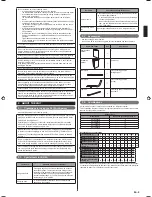
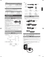
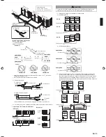
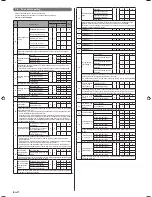
Energy-saving combination
Combination (HP)
8
10
12
14
16
18
20
22
24
26
28
Outdoor Unit 1 (HP)
–
–
–
–
8
–
–
14
8
10
12
Outdoor Unit 2 (HP)
–
–
–
–
8
–
–
8
8
8
8
Outdoor Unit 3 (HP)
–
–
–
–
–
–
–
–
8
8
8
Maximum Connectable
Indoor Unit
*
*
*
*
30
*
*
33
36
39
42
Combination (HP)
30
32
34
36
38
40
42
44
46
48
Outdoor Unit 1 (HP)
14
12
14
14
–
14
14
16
–
–
Outdoor Unit 2 (HP)
8
12
12
14
–
14
14
14
–
–
Outdoor Unit 3 (HP)
8
8
8
8
–
12
14
14
–
–
Maximum Connectable
Indoor Unit
45
48
48
48
*
48
48
48
*
*
* Means that the energy-saving combination is unavailable.
When connecting outdoor units, install the outdoor unit with the largest nominal system capac-
ity nearest to the refrigerant pipe and indoor unit, followed by those with lesser nominal system
capacities. (Outdoor unit 1
≥
Outdoor unit 2
≥
Outdoor unit 3)
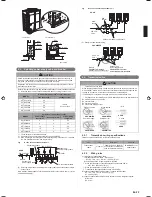
Optional parts
2. 5.
CAUTION
The following parts are optional parts speci
fi
c to R410A refrigerant.
Do not use parts other than those listed below.
Outdoor unit branch kit
2. 5. 1.
Model
Total cooling capacity of indoor unit (kW)
UTP-CX567A, UTR-CP567X
ALL
Separation tube
2. 5. 2.
Model
Total cooling capacity of indoor unit (kW)
UTP-AX090A , UTR-BP090X
28.0 or less
UTP-AX180A , UTR-BP180X
28.1 to 56.0
UTP-AX567A , UTR-BP567X
56.1 or more
Header
2. 5. 3.
3-6 branches
3-8 branches
Total cooling capacity of indoor unit (kW)
UTR-H0906L
UTR-H0908L
28.0 or less
UTR-H1806L
UTR-H1808L
28.1 to 56.0
INSTALLATION WORK
3.
Please obtain the approval of the customer when selecting the location of installation
and installing the main unit.
Selecting an installation location
3. 1.
WARNING
Install the unit in a location that can withstand its weight, and where it will not topple
or fall.
Calculate the proper refrigerant concentration if you will be installing it in an en-
closed location.
Total amount of replenished refrigerant in refrigerant facility (kg)
≤
Refrigerant concentration (kg/m
3
)
Capacity of smallest room where unit is installed (m
3
)
(0.3kg/m
3
)
If the results of the calculation exceed the concentration limit, increase the room
surface area or install a ventilation duct.
CAUTION
Select an installation location by observing the following precautions:
Install the unit level. (Within 3 degrees)
Install this unit in a location with good ventilation.
If the unit must be installed in an area within easy reach of the general public, install
as necessary a protective fence or the like to prevent their access.
Install the unit in an area that would not inconvenience your neighbors, as they could
be affected by the air
fl
ow coming out from the outlet, noise, or vibration.
If it must be installed in proximity to your neighbors, be sure to obtain their approval.
If the unit is installed in a cold region that is affected by snow accumulation, snow fall,
or freezing, take appropriate measures to protect it from those elements.
To ensure a stable operation, install inlet and outlet ducts.
Install the unit in an area that would not cause problems even if the drain water is
discharged from the unit. Otherwise, provide drainage that would not affect people or
objects.
CAUTION
Install the unit in an area that has no heat sources, vapors, or the risk of the leakage
of
fl
ammable gas in the vicinity.
Install the unit in an area that is away from the exhaust or vent ports that discharge
vapor, soot, dust, or debris.
Install the indoor unit, outdoor unit, power supply cable, transmission cable and
remote control cable at least 1 meter away from a television or radio.
The purpose of this is to prevent TV reception interference or radio noise. (Even if
they are installed more than 1 meter apart, you could still receive noise under some
signal conditions.)
Keep the length of the piping of the indoor and outdoor units within the allowable
range.
For maintenance purposes, do not bury the piping.
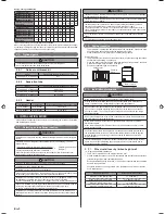
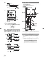
Drain processing
3. 2.
The drain water is discharged from the bottom of the equipment. Construct a drain
•
ditch around the base and discharge the drain water properly.
When installing on a roof, perform
fl
oor waterproo
fi
ng properly.
•
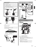
Drain processing:
The drain water from the base of the outdoor unit may generate during operations.
•
Perform drain processing, as necessary.
When you want to prevent the drain water from leaking at the perimeter, construct
•
a ditch for the drain water as shown in the
fi
gure.
Provide a central drain pan, as necessary.
•
Outdoor unit
10mm or more
50mm or
more
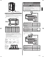
Installation dimensions
3. 3.
CAUTION
When installing the outdoor unit, pay attention to the following items.
Provide suf
fi
cient installation space, such as transportation route, maintenance
space, ventilation space, refrigerant piping space, and passageways.
Pay attention to the speci
fi
cations of the installation space as shown in the
fi
gure.
If the unit is not installed according to speci
fi
cations, it may cause short circuit or
poor performance. The unit may be prone to lapse into non-operation due to high
pressure protection.
Do not place obstructions in the air
fl
ow outlet direction. If there is an obstruction in
the outlet direction, install an outlet duct.
When there is a wall in front of the unit, provide a space of 500mm or more as
maintenance space.
When there is a wall at the left side of the unit, provide a space of 30mm or more
as maintenance space.
An outdoor temperature of 35 degrees in air-conditioned operation is assumed for
the installation space in this item. If the outdoor temperature exceeds 35 degrees
and the outdoor unit is operating at a load exceeding its rated ability, provide a
larger inlet space.
If you are installing more outdoor units than indicated here, please ensure suf
fi
cient
space or consult your distributing agent as it may affect the performance due to
short circuit and other problems.
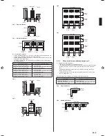
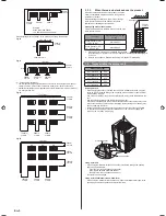
When install near by limited height wall
3. 3. 1.
Single and multiple installations
(1)
There are no restrictions on the height of the side wall.
•
Provide installation spaces L1 and L2 in accordance with the table below according
•
to the wall height (front side, rear side) conditions.
Provide installation spaces other than L1 and L2 in accordance with the conditions
•
shown in the
fi
gure below.
Ventilation resistance can be ignorable when the distance from a wall or product,
•
etc. is larger than 2m.
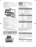
Wall height condition
Necessary installation space
When H1 is 1500 (mm) or less
L1
≥
500 (mm)
When H1 is 1500 (mm) or more
L1
≥
500+h1÷2 (mm)
When H2 is 500 (mm) or less
L2
≥
100 (mm)
When H2 is 500 (mm) or more
L2
≥
100+h2÷2 (mm)
9378945104-01_IM.indb Sec1:3
9378945104-01_IM.indb Sec1:3
2013-3-12 14:08:13
2013-3-12 14:08:13


