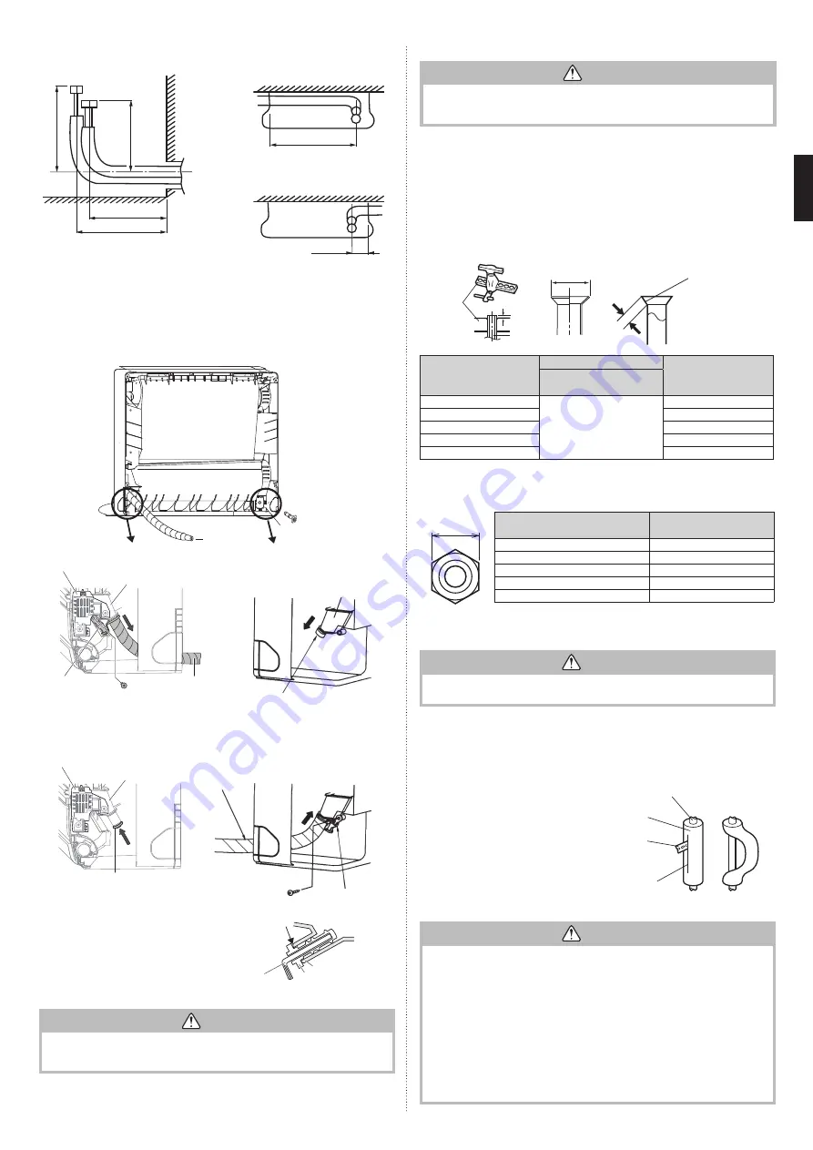
background image

En-7


Rear piping


Left piping

Center of 
wall hole

130 mm

Floor

280 mm

245 mm

Back wall

100 mm

Back wall

690 mm


Right piping

30 mm

Back wall


Left and right replacement of drain hose

The drain hose can be connected at either side of the indoor unit.

The unit has been shipped with the drain hose connected at left (viewed from the back of 
the unit) and the drain cap applied at right.
(1) Remove the both side panels.
(2) Remove the screw and remove the drain holder from drain pan.
(3) Pull out the drain cap.
(4)  Connect the drain hose to the right, attach the screw and insert the drain cap to the left.

Drain 
hose

Drain cap

Drain pan

Drain hose

Drain holder

Screw

Drain pan

Drain cap

Refrigerant leakage sensor

NOTE:

   When attaching/removing the drain holder and drain hose on the refrigerant leak-

age sensor side, be very careful not to give a shock to the sensor.

Drain holder

Drain hose

Screw

Drain cap

Drain pan

Refrigerant leakage sensor


Installation method of Drain cap

Use a hexagonal wrench (4 mm at opposite side) 
to insert the drain cap, till the drain cap contacts 
the tip of drain cook.

No gap

Drain cock

Drain cap

Hexagon 
wrench

 CAUTION

Insert the drain hose and drain cap into the drain port, making sure that it comes 
in contact with the back of the drain port, and then mount it. If the drain hose is not 
connected properly, leaking will occur.

3.3.6. Pipe connection

 CAUTION

Tighten the flare nuts with a torque wrench using the specified tightening method. 
Otherwise, the flare nuts could break after a prolonged period, causing refrigerant to 
leak and generate hazardous gas if the refrigerant comes into contact with a flame.


Flaring

Use special pipe cutter and flare tool designed for R410A or R32 pipework.
(1)  Cut the connection pipe to the necessary length with a pipe cutter.
(2)  Hold the pipe downward so that cuttings will not enter the pipe and remove any burrs.
(3)  Insert the flare nut (always use the flare nut attached to the indoor unit(s) and outdoor 

unit or branch box respectively) onto the pipe and perform the flare processing with a 
flare tool. Use the special R410A or R32 flare tool, or the conventional flare tool. Leak-
age of refrigerant may result if other flare nuts are used.

(4)  Protect the pipes by pinching them or with tape to prevent dust, dirt, or water from 

entering the pipes.

Die

A

Pipe

B

L

Check if [L] is flared uniformly 
and is not cracked or scratched.

Pipe outside diameter 

[mm (in.)]

Dimension A [mm]

Dimension B [mm]

Flare tool for R32, 

clutch type

6.35 (1/4)

0 to 0.5

9.1

9.52 (3/8)

13.2

12.70 (1/2)

16.6

15.88 (5/8)

19.7

19.05 (3/4)

24.0

When using conventional flare tools to flare R32 pipes, the dimension A should be approx-
imately 0.5 mm more than indicated in the table (for flaring with R32 flare tools) to achieve 
the specified flaring. Use a thickness gauge to measure the dimension A. 

Width across 

flats

Pipe outside diameter 

[mm (in.)]

Width across flats 

of flare nut [mm]

6.35 (1/4)

17

9.52 (3/8)

22

12.70 (1/2)

26

15.88 (5/8)

29

19.05 (3/4)

36

NOTE:

 The flare nut specification is compliant with ISO14903.


Bending pipes

 CAUTION

 •  To prevent breaking of the pipe, avoid sharp bends. 
 •  If the pipe is bent repeatedly at the same place, it will break.

•   The pipes are shaped by your hands. Be careful not to collapse them.
•   Bend R70 mm or more with a pipe bender.
•   Do not bend the pipes in an angle more than 90°.
•   When pipes are repeatedly bend or stretched, the material will harden, making it difficult 

to bend or stretch them anymore.

•   Do not bend or stretch the pipes more than 3 times.


   When bending the pipe, do not bend it as 

is. The pipe will be collapsed. In this case, 
cut the insulating pipe with a sharp cutter as 
shown on the right, and bend it after expos-
ing the pipe. After bending the pipe as you 
want, be sure to put the heat insulating pipe 
back on the pipe, and secure it with tape.

Pipe

Insulating 
pipe

Cutter

Cut line


Flare connection

 CAUTION

•  Be sure to install the pipe against the port on the indoor unit correctly. If the center-

ing is improper, the flare nut cannot be tightened smoothly. If the flare nut is forced 
to turn, the threads will be damaged.

•  Do not remove the flare nut from the indoor unit pipe until immediately before con-

necting the connection pipe.

•  Hold the torque wrench at its grip, keeping it in the right angle with the pipe, in order 

to tighten the flare nut correctly. 

•  Tighten the flare nuts with a torque wrench using the specified tightening method. 

Otherwise, the flare nuts could break after a prolonged period, causing refrigerant to 
leak and generate hazardous gas if the refrigerant comes into contact with a flame.

•  Connect the piping so that the control box cover can easily be removed for servic-

ing when necessary.

•  In order to prevent water from leaking into the control box, make sure that the pip-

ing is well insulated.

9378533080-04_IM.indb   7

9378533080-04_IM.indb   7

2022/2/14   15:13:14

2022/2/14   15:13:14

Содержание AGHG12KVCA

Страница 1: ...ut continuously operating ignition sources for example open flames an operating gas appliance or an operating electric heater Do not pierce or burn Be aware that refrigerants may not contain an odour Keep any required ventilation openings clear of obstruction If the power cable or the connection cable is damaged it must be replaced by the manufacturer its service agent or similar qualified persons...

Страница 2: ...quipment being used is suitable for use with flam mable refrigerants i e nonsparking adequately sealed or intrinsically safe 2 4 Presence of fire extinguisher If any hot work is to be conducted on the refrigeration equipment or any associated parts appropriate fire extinguishing equipment shall be available at hand Have a dry powder or CO2 fire extinguisher adjacent to the charging area 2 5 No ign...

Страница 3: ...ore carrying out this procedure it is essential that the technician is completely familiar with the equipment and all its details It is recommended good practice that all refrigerants are recovered safely Prior to the task being carried out an oil and refrigerant sample shall be taken in case analysis is required prior to re use of reclaimed refrigerant It is essential that electrical power is ava...

Страница 4: ...be purchased separately Additional materials Connection pipe assembly Wall cap Connection cable 4 conductor Saddle Wall pipe Drain hose Decorative tape Tapping screws Vinyl tape Putty Sealant Refrigeration armored tape Insulated staples or clamps for connecting wire refer to your electrical cables Clamps or saddles to secure refrigerant pip ing Refrigeration lubricant 1 1 2 3 Pipe requirement CAUT...

Страница 5: ...ote control cable at least 1 m away from a television or radio receivers The purpose of this is to prevent TV reception interference or radio noise Even if they are installed more than 1 m apart you could still receive noise under some signal conditions If children under 10 years old may approach the unit take preventive measures so that they cannot reach the unit When installing pipes shorter tha...

Страница 6: ...e top of the indoor unit on the indoor unit wall hook bracket 124 423 703 154 438 Unit mm WARNING Fix the indoor unit with 4 screws surely If improperly installed might cause to injury due to the toppling or falling Install the indoor unit at the place that has adequate strength Install the indoor unit so that the installed unit can withstand the weight of adult body weight If improperly installed...

Страница 7: ... from entering the pipes Die A Pipe B L Check if L is flared uniformly and is not cracked or scratched Pipe outside diameter mm in Dimension A mm Dimension B mm Flare tool for R32 clutch type 6 35 1 4 0 to 0 5 9 1 9 52 3 8 13 2 12 70 1 2 16 6 15 88 5 8 19 7 19 05 3 4 24 0 When using conventional flare tools to flare R32 pipes the dimension A should be approx imately 0 5 mm more than indicated in t...

Страница 8: ...cable clamp always fasten the cable at the plastic jacket portion but not at the insulator portion If the insulator is chafed electric leakage may occur Always connect the ground earth wire Improper earthing grounding work can cause electric shocks Do not use the ground earth screw for the indoor unit to the outdoor unit unless it is specified When the flare nut is tightened properly by your hand ...

Страница 9: ...ON WORK 4 1 Before install optional remote controller When you use optional remote controller some functions may not be used Please use the recommended optional remote controller CAUTION Before installing be sure to disconnect all power supply Don t touch the heat exchanger During installing or removing operation be sure not to have wire caught by parts or draw it hard Or it may result troubles to...

Страница 10: ...he following condition DC 12 V to 24 V 1 mA to 15 mA Operation behavior Input signal type Edge ON OFF When function setting is Operation Stop mode 1 Input signal Command OFF ON Operation ON OFF Stop When function setting is Forced stop mode Input signal Command OFF ON Forced stop ON OFF Normal When the forced stop is triggered indoor unit stops and Operation Stop operation by a remote controller i...

Страница 11: ...fore reconnecting it The function setting will not become active unless the power supply is disconnected and then reconnected 5 1 Function details Filter sign Select appropriate intervals for displaying the filter sign on the indoor unit according to the estimated amount of dust in the air of the room If the indication is not required select No indication 03 Factory setting Function num ber Settin...

Страница 12: ...s Error status Setting record Record any changes to the settings in the following table Function number Function setting Setting value 11 Filter sign 30 Room temperature control for indoor unit sensor Cooling 31 Heating 35 Room temperature control for wired remote controller sensor Cooling 36 Heating 40 Auto restart 42 Room temperature sensor switching 44 Remote controller custom code 46 External ...

Страница 13: ...d remote controller error codes will ap pear on the remote control display Refer to the lamp blinking patterns and error codes in the table An error display is displayed only during operation The error code table contains errors irrelevant to this product as well Error display on the indoor unit TIMER LED1 TIMER Lamp orange LED2 OPERATION lamp green LED3 ECONOMY lamp green OPERATION ECONOMY For wi...

Страница 14: ...otor 1 error Error display Error code Description LED1 orange LED2 green LED3 green 8 9 98 Outdoor unit fan motor 2 error 9 9 99 4 way valve error 10 9 9A Coil expansion valve error 1 10 A1 Discharge temp error 3 10 A3 Compressor temp error 4 10 A4 High pressure error 5 10 A5 Low pressure error 8 10 A8 Refrigerant leakage suspicion 11 10 AC Heat sink temp error 2 13 J2 Branch boxes error Multi spl...

Отзывы: