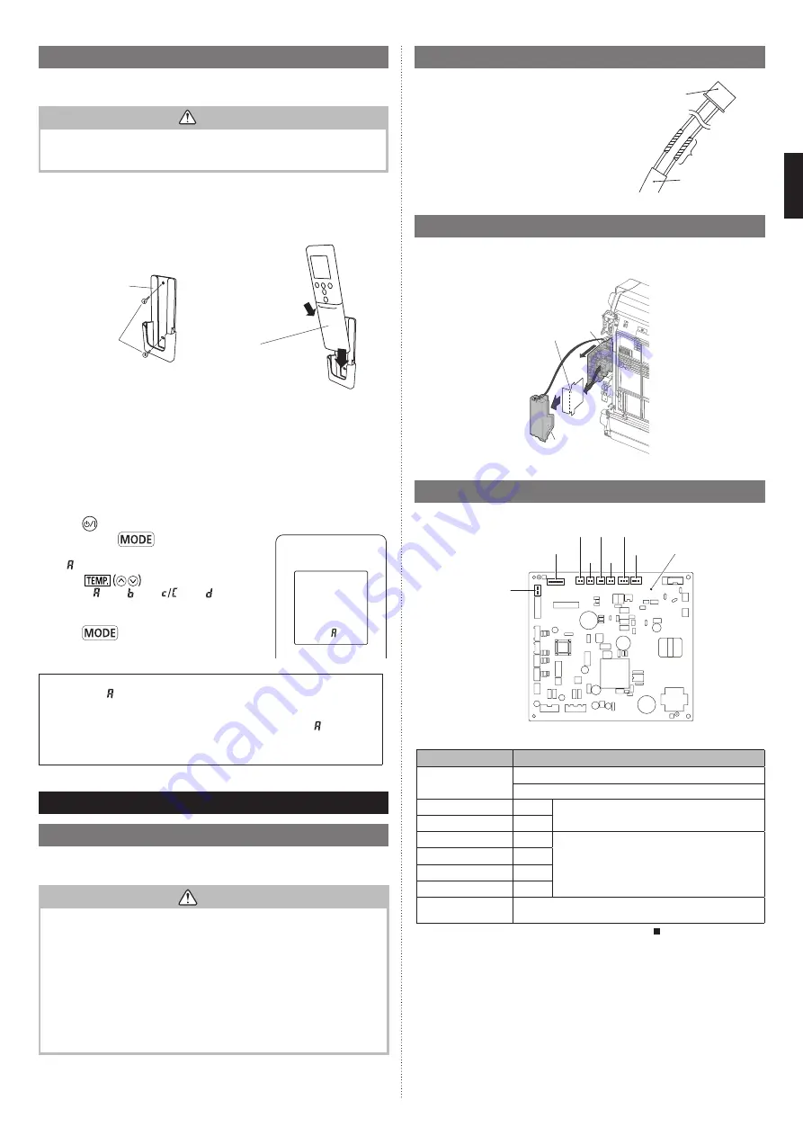
En-9
1]
1
3.5. Remote controller installation
Check that the indoor unit correctly receives the signal from the remote controller, then
install the remote controller holder.
CAUTION
Do not install the remote controller holder in the following conditions:
• Any places exposed in direct sunlight
• Positions affected by the heat from a stove or heater
3.5.1. Remote controller holder installation
•
Install the remote controller a maximum distance of 7 m from the remote control signal
receiver. After installing the remote controller, check that it operates correctly.
•
Install the remote controller holder to a wall, pillar, etc. with the tapping screw.
Remote controller
holder
Tapping
screw
(small)
(1) Set
Remote
controller
(2) Down
3.5.2. Remote controller custom setting
By setting custom code of indoor unit and remote controller, you can specify the air
conditioner which the remote controller controls.
When two or more air conditioners are in the room and you wish to operate them
separately, set the custom code (4 selections possible).
NOTE:
If custom codes is different between the indoor unit and the remote controller, the
indoor unit cannot receive a signal from the remote controller.
How to set the remote controller custom code
(1)
Press
until only the clock is displayed on the remote controller display.
(2)
Press and hold
for more than 5 seconds.
The current custom code will be displayed (initially set
to ).
(3) Press
to change the custom code be-
tween A ( )
↔
B ( )
↔
C (
)
↔
D ( ).
* Match the custom code on the display to the air con-
ditioner custom code.
(4) Press
again.
The custom code will be set.
The display will return to the clock display.
• To change the air conditioner custom code, contact an authorized service personnel
(initially set to ).
• If you do not press any buttons for 30 seconds after the custom code is displayed,
the display returns to the clock display. In this case, repeat the setting from step (2).
• Depending on the remote controller, the custom code may return to when replac-
ing the batteries. In this case, reset the custom code as necessary. If you do not
know the air conditioner custom code, try each code until you find the code which
operates the air conditioner.
4. OPTIONAL INSTALLATION WORK
4.1. Before install optional remote controller
• When you use optional remote controller, some functions may not be used.
• Please use the recommended optional remote controller.
CAUTION
• Before installing, be sure to disconnect all power supply.
• Don’t touch the heat exchanger.
• During installing or removing operation, be sure not to have wire caught by parts or
draw it hard. Or it may result troubles to the air-conditioner.
• Avoid place in direct sunlight.
• Select place that will not be affected by the heat from a stove, etc.
• Before setting up the optional kit, please confirm whether air-conditioner can receive
the signal.
• Do not connect the optional remote controller to the terminal for power supply.
• When connecting the optional remote controller with the indoor unit, please use the
connecting cable packaged up with the optional remote controller.
• Recommended cable length of optional remote controller is 10 m (33 ft). Make sure
to do insulate of connecting part when extended the cable.
4.2. External input/output Wire modification
(1) Remove insulation from wire attached to wire
kit connector. Remove insulation from locally
purchased cable. Use crimp type insulated butt
connector to join the cable and wire kit wire.
(2) Connect the wire and locally purchased wire.
(supplied with external connect kit)
Important:
Be sure to solder wires to connect. Be sure to
insulate the connection between the wires.
Option parts
External input/
output wire
Cable
(Locally purchased)
Insulated
connection
4.3. Side panel L and control cover removal
]
(1) Refer to “3.2. Side panel L, R removal and installation” to remove the side panel L.
(2) Remove the control cover.
(3) Remove the control inner cover.
PCB
Control
inner cover
Control cover
4.4. Connecting cable to control board connector
• Connect the cable the circuit board.
PCB
P 190
P 210
CN
20
CN 14
CN 15
CN 21
CN
22
CN 23
For details on how to install optional parts, refer to the installation manual included in
each item.
Connection No.
Option type
P190
Wired remote controller (via the Communication kit)
Simple remote controller (via the Communication kit)
CN14*
1
External input
CN15*
2
CN20*
1
External output
CN21*
2
CN22*
3
CN23*
4
P210
Other optional parts (WLAN adapter, Modbus converter, KNX
convertor, etc.) can be connectable.
*: For external input and external output setting, refer to the “ Combination of external
input and output” in “5. FUNCTION SETTING”.
9378533080-04_IM.indb 9
9378533080-04_IM.indb 9
2022/2/14 15:13:14
2022/2/14 15:13:14


