PARAMETERS
5
5-17
n
Each sequence input/output signal can be monitored in the trace screen of the PC loader.
The ready [RDY] and positioning end [PSET] signals among sequence output signals are fixed at the
OUT terminals.
O: Terminal allocation and waveform trace are possible.
Sequence input signal
CONT
allocation
PC loader
Sequence output signal
OUT
allocation
PC loader
Operation command [RUN]
¡
¡
Alarm detection: a-contact
¡
¡
Reset [RST]
¡
¡
Alarm detection: b-contact
¡
¡
+ overtravel
[+OT]
¡
¡
Dynamic brake
¡
¡
- overtravel
[-OT]
¡
¡
Overtravel detection
¡
¡
Forced stop
[EMG]
¡
¡
Forced stop detection
¡
¡
P-action
¡
¡
Ready
[RDY]
x (Fixed)
¡
Deviation clearance
¡
¡
Positioning end
[PSET]
x (Fixed)
¡
Zero deviation*
H
¡
External regenerative
resistor overheat
¡
¡
Zero speed*
H
¡
Torque limit detection*
H
¡
Anti-resonance frequency
selection 0
¡
¡
CPU ready*
H
¡
Anti-resonance frequency
selection 1
¡
¡
Manual forward rotation
[FWD]*
H
¡
(For test op.)
Manual reverse rotation
[REV]*
H
¡
(For test op.)
* Only waveform at the PC loader can be traced.
Terminals cannot be allocated.
7 CA
8
*CA
CN
1
CN
1
CN
1
CN
1
1
9
PPI
2
1
*CB
20
CB
FZ 25
M5 26
FFA 9
FFB
11
*FFB
1
2
FFZ 23
*FFZ 24
*FFA
1
0
1
P24
2 CONT
1
5 CONT4
3
CONT2
6 CONT5
1
4
M24
4
CONT3
OUT
1
1
5
OUT2
1
6
RDY
1
7
PSET
1
8
Servo amplifier
M5
1
3
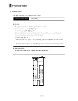
Terminal allocation of connector 1 (CN1) of servo amplifier and trace screen of PC loader
Содержание GYN101CAG-G09
Страница 1: ...FUJI AC SERVO SYSTEM USER S MANUAL MEH395 ...
Страница 2: ......
Страница 10: ......
Страница 11: ...1 1 Outline 1 2 Items to be confirmed 1 3 Servomotor 1 4 Servo amplifier 1 5 Type designation OUTLINE ...
Страница 20: ...1 Outline 1 10 MEMO ...
Страница 21: ...2 1 Servomotor 2 2 Servo amplifier INSTALLATION ...
Страница 32: ...2 INSTALLATION 2 12 MEMO ...
Страница 46: ...3 WIRING 3 14 MEMO ...
Страница 52: ...3 WIRING 3 20 MEMO ...
Страница 64: ...3 WIRING 3 32 MEMO ...
Страница 65: ...4 1 Test operation in two stages 4 2 First stage 4 3 Second stage TEST OPERATION ...
Страница 70: ...4 TEST OPERATION 4 6 MEMO ...
Страница 85: ...PARAMETERS 5 5 15 MEMO ...
Страница 125: ...6 1 Basic adjustment 6 2 Application adjustment 6 3 Adjustment requiring high speed response ADJUSTMENT OF SERVO ...
Страница 132: ...6 ADJUSTMENT OF SERVO 6 8 MEMO ...
Страница 133: ...7 1 Vibration control 7 2 Command follow up control 7 3 Position gain and limit added when setting SPECIAL ADJUSTMENT ...
Страница 164: ...8 KEYPAD PANEL 8 18 MEMO ...
Страница 165: ...INSPECTION AND MAINTENANCE 9 1 Inspection 9 2 Memory back up 9 3 Fault display 9 4 Maintenance and discharge ...
Страница 186: ...9 INSPECTION AND MAINTENANCE 9 22 MEMO ...
Страница 226: ...11SPECIFICATIONS 11 14 MEMO ...
Страница 234: ...11SPECIFICATIONS 11 22 Servo amplifier Unit mm Unit mm Unit mm ...
Страница 235: ...APPENDIXES Inertia moment calculation Load torque Timing chart ...
Страница 250: ...APPENDIXES Appendix 16 MEMO ...
Страница 251: ...APPENDIXES Appendix 17 MEMO ...


