


5
PARAMETERS
5-8
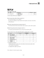
Basic setting parameter #03
No.
Name
Setting range
Initial value
Change
03
Pulse string input
form
0: Command pulse / command sign,
1: Forward / reverse rotation pulse,
2: Two signals with 90-degree phase
difference
1
Power
The form of the signal added to the pulse string input terminal can be selected.
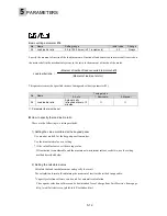
The form of pulse strings added to the [CA], [*CA], [CB] and [*CB] pulse string input terminals of the
servo amplifier can be specified. The maximum input frequency is 1.0MHz.
n
Command pulse/command sign (Setting of basic setting parameter 03: 0)
The rotation amount is indicated with the command pulse while the direction of rotation is indicated
with the command sign.
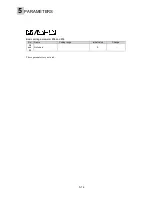
- Differential input
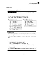
- Open collector input
Forward rotation command
CA
*CA
CB
*CB
Reverse rotation command
The arrow "
" shown in the figure above is triggered at each pulse count timing.
t
1≦1
00[nsec]
t2
≦1
00[nsec]
t3
≧
480[nsec
]
t4
≧
480[nsec
]
t6
≧
500[nsec]
t7
≧
500[nsec]
t8
≦1
00[nsec]
90%
90%
90%
90%
1
0%
1
0%
1
0%
1
0%
t3
t3
t3
t3
t
1
t
1
t
1
t
1
t2
t2
t2
t2
90%
90%
90%
90%
1
0%
1
0%
1
0%
1
0%
t6
t6
t6
t6
t7
t7
t7
t7
t8
t8
t8
t8
t4
t4
t4
t4
↑↓
Forward rotation command
*CA
*CB
Reverse rotation command
"ON" shown in the figure above indicates the active transistor and low signal level.
The arrow " " shown in the figure above is triggered at each pulse count timing.
90%
90%
90%
90%
1
0%
1
0%
1
0%
1
0%
t
1
t
1
t
1
t
1
t3
t3
t3
t3
t2
t2
t2
t2
t4
t4
t4
t4
t
1≦
0.2[
μ
sec]
t2
≦
0.2[
μ
sec]
t3
≧
2[
μ
sec
]
t4
≧
2[
μ
sec
]
t6
≧
2.5[
μ
sec]
t7
≧
2.5[
μ
sec]
t8
≦
0.2[
μ
sec]
90%
90%
90%
90%
1
0%
1
0%
1
0%
1
0%
t6
t6
t6
t6
t8
t8
t8
t8
t7
t7
t7
t7
ON
ON
ON
ON
ON
ON
ON
ON
ON
ON
ON
ON
ON
ON
ON
ON
ON
ON
ON
ON
ON
ON
ON
ON
ON
ON
ON
ON
↓
Содержание GYN101CAG-G09
Страница 1: ...FUJI AC SERVO SYSTEM USER S MANUAL MEH395 ...
Страница 2: ......
Страница 10: ......
Страница 11: ...1 1 Outline 1 2 Items to be confirmed 1 3 Servomotor 1 4 Servo amplifier 1 5 Type designation OUTLINE ...
Страница 20: ...1 Outline 1 10 MEMO ...
Страница 21: ...2 1 Servomotor 2 2 Servo amplifier INSTALLATION ...
Страница 32: ...2 INSTALLATION 2 12 MEMO ...
Страница 46: ...3 WIRING 3 14 MEMO ...
Страница 52: ...3 WIRING 3 20 MEMO ...
Страница 64: ...3 WIRING 3 32 MEMO ...
Страница 65: ...4 1 Test operation in two stages 4 2 First stage 4 3 Second stage TEST OPERATION ...
Страница 70: ...4 TEST OPERATION 4 6 MEMO ...
Страница 85: ...PARAMETERS 5 5 15 MEMO ...
Страница 125: ...6 1 Basic adjustment 6 2 Application adjustment 6 3 Adjustment requiring high speed response ADJUSTMENT OF SERVO ...
Страница 132: ...6 ADJUSTMENT OF SERVO 6 8 MEMO ...
Страница 133: ...7 1 Vibration control 7 2 Command follow up control 7 3 Position gain and limit added when setting SPECIAL ADJUSTMENT ...
Страница 164: ...8 KEYPAD PANEL 8 18 MEMO ...
Страница 165: ...INSPECTION AND MAINTENANCE 9 1 Inspection 9 2 Memory back up 9 3 Fault display 9 4 Maintenance and discharge ...
Страница 186: ...9 INSPECTION AND MAINTENANCE 9 22 MEMO ...
Страница 226: ...11SPECIFICATIONS 11 14 MEMO ...
Страница 234: ...11SPECIFICATIONS 11 22 Servo amplifier Unit mm Unit mm Unit mm ...
Страница 235: ...APPENDIXES Inertia moment calculation Load torque Timing chart ...
Страница 250: ...APPENDIXES Appendix 16 MEMO ...
Страница 251: ...APPENDIXES Appendix 17 MEMO ...