WIRING
3
3-7
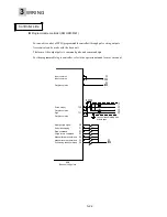
(4) Sequence input/output terminal
Connect the signal cable of a host controller to connector 1 (CN1) of the servo amplifier.
n
List of sequence functions
Terminal
symbol
Pin No. Name
Function and meaning
P24
M24
1
14
Power supply for
sequence input/output
Power supply input for sequence input/output signals
(+24VDC, 0.3A)
CONT1
CONT2
CONT3
CONT4
CONT5
2
3
4
5
6
Sequence input
Sequence input signals. The following signals are
allocated by the factory settings.
(+24VDC, 10 mA)
CONT 1: Operation command (RUN)
CONT 2: Reset (RST)
CONT 3: (Not specified)
CONT 4: (Not specified)
CONT 5: (Not specified)
OUT1
OUT2
RDY
PSET
15
16
17
18
Sequence output
Sequence output signals. The following signals are
allocated by the factory settings.
(Max. +30VDC / 50mA)
OUT 1: Alarm detection, a-contact
OUT 2: (Not specified)
RDY: Active when ready to turn
PSET: Active upon completion of positioning
PPI
CA
*CA
CB
*CB
19
7
8
20
21
Pulse string input
PPI: Power supply input for open collector (24 VDC +/-5%)
- Differential input
CA, *CA, CB, *CB (max. input frequency: 1 MHz)
- Open collector input
*CA, *CB (max. input frequency: 200 kHz)
The pulse string form can be chosen from command pulse
and sign, forward/reverse rotation pulse, and two signals
having 90-degree phase difference.
FFA
*FFA
FFB
*FFB
FFZ
*FFZ
FZ
M5
9
10
11
12
23
24
25
26 ,13
Frequency dividing
output
Frequency dividing output terminals. Two signals having
90-degree phase difference in proportion to the rotation of
the servomotor are output. (Differential output)
The FZ terminal is an open-collector output.
(Max. +30VDC, 50mA)
M5: Reference potential
NC
22
No connection
Do not connect this terminal.
* Terminals having the same name (M5) are connected internally. They are not connected with terminal M24.
FZ
25
FFZ
23
*CB
21
PPI
19
RDY
17
OUT1
15
M5
13
FFB
11
FFA
9
CA
7
CONT4
5
CONT2
3
P24
1
*FFB
12
*FFA
10
*CA
8
CONT5
6
CONT3
4
CONT1
2
24
NC
22
CB
20
PSET
18
OUT
16
M24
14
26 M5
*FFZ
Compatible connector on cable side
Soldered plug: 10126-3000V
Shell kit
: 10326-52A0-008
Содержание GYN101CAG-G09
Страница 1: ...FUJI AC SERVO SYSTEM USER S MANUAL MEH395 ...
Страница 2: ......
Страница 10: ......
Страница 11: ...1 1 Outline 1 2 Items to be confirmed 1 3 Servomotor 1 4 Servo amplifier 1 5 Type designation OUTLINE ...
Страница 20: ...1 Outline 1 10 MEMO ...
Страница 21: ...2 1 Servomotor 2 2 Servo amplifier INSTALLATION ...
Страница 32: ...2 INSTALLATION 2 12 MEMO ...
Страница 46: ...3 WIRING 3 14 MEMO ...
Страница 52: ...3 WIRING 3 20 MEMO ...
Страница 64: ...3 WIRING 3 32 MEMO ...
Страница 65: ...4 1 Test operation in two stages 4 2 First stage 4 3 Second stage TEST OPERATION ...
Страница 70: ...4 TEST OPERATION 4 6 MEMO ...
Страница 85: ...PARAMETERS 5 5 15 MEMO ...
Страница 125: ...6 1 Basic adjustment 6 2 Application adjustment 6 3 Adjustment requiring high speed response ADJUSTMENT OF SERVO ...
Страница 132: ...6 ADJUSTMENT OF SERVO 6 8 MEMO ...
Страница 133: ...7 1 Vibration control 7 2 Command follow up control 7 3 Position gain and limit added when setting SPECIAL ADJUSTMENT ...
Страница 164: ...8 KEYPAD PANEL 8 18 MEMO ...
Страница 165: ...INSPECTION AND MAINTENANCE 9 1 Inspection 9 2 Memory back up 9 3 Fault display 9 4 Maintenance and discharge ...
Страница 186: ...9 INSPECTION AND MAINTENANCE 9 22 MEMO ...
Страница 226: ...11SPECIFICATIONS 11 14 MEMO ...
Страница 234: ...11SPECIFICATIONS 11 22 Servo amplifier Unit mm Unit mm Unit mm ...
Страница 235: ...APPENDIXES Inertia moment calculation Load torque Timing chart ...
Страница 250: ...APPENDIXES Appendix 16 MEMO ...
Страница 251: ...APPENDIXES Appendix 17 MEMO ...


