


TEST OPERATION
4
4-3
4-2) First stage
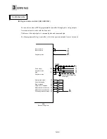
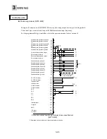
Connect the servo amplifier and servomotor to perform test operation. Refer to Chapter 3 for the wiring
method.
Do not connect the servomotor to the mechanical system when performing test operation.
Check the following items in the first stage.
<Items to be checked>
1. Check the power supply wiring of the servo amplifier (L1, L2 and L3).
2. Check the servomotor power cables (U, V and W) and encoder cable.
3. Check if the servo amplifier and servomotor function correctly.
4. Check parameter #4 (switching direction of rotation).
n
Test operation procedure
(1) Fix the servomotor so that it will not fall.
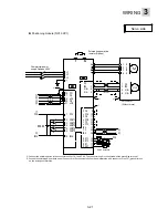
(2) Referring to Chapter 3, connect cables to the servo amplifier and the servomotor.
(3) Turn the power on.
Check the charge LED (i) and keypad panel indication (ii).
Fix securely.
Mount nothing on the motor shaft.
i) Check the charge LED.
Red LED lights up in the normal
state.
ii) Check the touch panel indication.
When faulty
A value between 1
and 19 blinks.
(Alarm detection)
When correct
* If an alarm is detected, turn the power off, check wiring, and refer to Chapter 9.
Содержание GYN101CAG-G09
Страница 1: ...FUJI AC SERVO SYSTEM USER S MANUAL MEH395 ...
Страница 2: ......
Страница 10: ......
Страница 11: ...1 1 Outline 1 2 Items to be confirmed 1 3 Servomotor 1 4 Servo amplifier 1 5 Type designation OUTLINE ...
Страница 20: ...1 Outline 1 10 MEMO ...
Страница 21: ...2 1 Servomotor 2 2 Servo amplifier INSTALLATION ...
Страница 32: ...2 INSTALLATION 2 12 MEMO ...
Страница 46: ...3 WIRING 3 14 MEMO ...
Страница 52: ...3 WIRING 3 20 MEMO ...
Страница 64: ...3 WIRING 3 32 MEMO ...
Страница 65: ...4 1 Test operation in two stages 4 2 First stage 4 3 Second stage TEST OPERATION ...
Страница 70: ...4 TEST OPERATION 4 6 MEMO ...
Страница 85: ...PARAMETERS 5 5 15 MEMO ...
Страница 125: ...6 1 Basic adjustment 6 2 Application adjustment 6 3 Adjustment requiring high speed response ADJUSTMENT OF SERVO ...
Страница 132: ...6 ADJUSTMENT OF SERVO 6 8 MEMO ...
Страница 133: ...7 1 Vibration control 7 2 Command follow up control 7 3 Position gain and limit added when setting SPECIAL ADJUSTMENT ...
Страница 164: ...8 KEYPAD PANEL 8 18 MEMO ...
Страница 165: ...INSPECTION AND MAINTENANCE 9 1 Inspection 9 2 Memory back up 9 3 Fault display 9 4 Maintenance and discharge ...
Страница 186: ...9 INSPECTION AND MAINTENANCE 9 22 MEMO ...
Страница 226: ...11SPECIFICATIONS 11 14 MEMO ...
Страница 234: ...11SPECIFICATIONS 11 22 Servo amplifier Unit mm Unit mm Unit mm ...
Страница 235: ...APPENDIXES Inertia moment calculation Load torque Timing chart ...
Страница 250: ...APPENDIXES Appendix 16 MEMO ...
Страница 251: ...APPENDIXES Appendix 17 MEMO ...