background image

WARNING

   THE COMPORNENTS IDENTIFIED BY THE MARK 

“         ”

 ON THE SCHEMATHIC

   DIAGRAM AND IN THE PARTS LIST ARE CRITICAL FOR SAFETY.
   PLEASE REPLACE ONLY BY THE COMPONENTS SPECIFIED ON THE SCHEMATHIC
   DIAGRAM AND IN THE PARTS LIST.
   IF YOU USE WITH PART NUMBER UN-SPECIFIED, IT MAY RESULT IN A FIRE AND AN
   ELECTORICAL SHOCK.

FUJI PHOTO FILM CO.,LTD.

Ref.No.:ZM00509-100

Printed in Japan 2003.07(S.S.)

SERVICE MANUAL

  DIGITAL CAMERA

FinePix S5000

US/EU/EG/CA/GE/AS-Model

Содержание FinePix S5000

Страница 1: ...EASE REPLACE ONLY BY THE COMPONENTS SPECIFIED ON THE SCHEMATHIC DIAGRAM AND IN THE PARTS LIST IF YOU USE WITH PART NUMBER UN SPECIFIED IT MAY RESULT IN A FIRE AND AN ELECTORICAL SHOCK FUJI PHOTO FILM CO LTD Ref No ZM00509 100 Printed in Japan 2003 07 S S SERVICE MANUAL DIGITAL CAMERA FinePix S5000 US EU EG CA GE AS Model ...

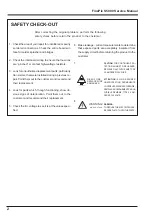
Страница 2: ... the original problem perform the following safety check before return the product to the costomer 1 Check the area of your repair for unsoldered or poorly sol dered connections Check the entire board sur face for solder splasher and bridges 2 Check the interboard wiring to ensure that no wires are pinched or contact high wattage resistors 3 Look for unauthorized replacement parts particuarly tran...

Страница 3: ...Schematic Diagram 30 3 18 CCD FPC ASSY Component Locations 31 3 19 RSW PWB ASSY Component Locations 31 3 20 MAIN PWB ASSY Component Locations 32 3 21 DCST PWB ASSY Component Locations 33 3 22 KSW PWB ASSY Component Locations 34 3 23 MSW PWB ASSY Component Locations 35 4 Adjustments 36 4 1 Adjustment Procedure of Parts Replacement 36 4 2 Measuring Devices 36 4 3 Jigs 36 4 4 Jig Connections 37 4 5 E...

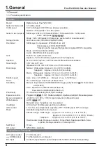
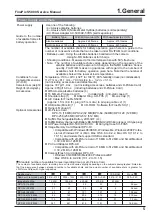
Страница 4: ...Approx 0 9 m to 2 0 m 3 0 ft to 6 6 ft Shutter speed Auto 2 sec to 1 2000 sec Manual 2 sec to 1 2000 sec Focus TTL contrast type Auto focus Manual focus Sensitivity Manual Equivalent to ISO200 400 800 Image quality fixed at for shots taken at ISO 800 Auto Equivalent to ISO160 200 at flash off Equivalent to ISO200 400 at flash on Photometry TTL 64 zones metering Multi Spot Average Exposure control ...

Страница 5: ...l 1 Optional Accessories xD Picture Card DPC 16 16 MB DPC 32 32 MB DPC 64 64 MB DPC 128 128 MB DPC 256 256 MB DPC 512 512 MB Fujifilm Rechargeable Battery 2HR 3UF 2 Fujifilm Battery charger with Battery BK NH BK NH2 With Euro type or UK type plug AC Power Adapter AC 5VH AC 5VHS Carrying Case SC FXS5 Image Memory Card Reader DPC R1 Compatible with Windows 98 98 SE Windows Me Windows 2000 Profes sio...

Страница 6: ...t is halved the EV decreases by 1 Frame rate fps The frame rate refers to the number of images frames that are photographed or played back per second For example when 10 frames are continuously photo graphed in a 1 second interval the frame rate is expressed as 10 fps For reference TV images are displayed at 30 fps JPEG Joint Photographics Experts Group A file format used for compressing and savin...

Страница 7: ...hooting button Focus mode selector lock switch Power switch Shutter button W Wide zoom button Photo mode button BACK button DISP Display button Battery cover MENU OK button 4 direction button T Tele zoom button Strap mount Viewfinder Diopter adjustment dial EVF LCD monitor selector button Tripod mount LCD monitor Indicator lamp Macro button Flash button ...

Страница 8: ...Manual Flash pop up button Strap mount Slot cover USB socket Mini B DC IN 5V power input socket A V OUT Audio visual output socket Self timer lamp Microphone Flash Flash control sensor AF Assist Illuminator Speaker xD Picture Card slot Lens ...

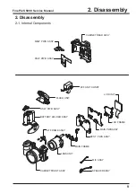
Страница 9: ...embly 2 1 Internal Components CABINET REAR ASSY LCD UNIT LENS UNIT MAIN PWB ASSY CABINET FRONT ASSY BATTERY HOLDER ASSY FLASH UNIT MIC ASSY SPEAKER ASSY EVF UNIT CONST RSW PWB ASSY MAIN FRAME DCST PWB ASSY LCD FRAME AF FRAME ASSY KSW PWB ASSY MSW PWB ASSY ...

Страница 10: ...y 1 Remove the three screws M1 7x3 5 2 Remove the two screws M1 7x5 3 Open the battery cover 4 Raise the R CABINET ASSY in the direction of the arrow 5 Remove the FFC Assembly Set the mode dial to the camera position and assemble it Assemble in the reverse order to disassembly 1 1 2 3 4 5 ...

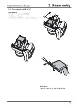
Страница 11: ... S5000 Service Manual 2 3 Removing the LCD UNIT Disassembly 1 Remove the two screws M1 7x2 5 2 Remove the connector 3 Raise the LCD UNIT in the direction of the arrow Assembly Assemble in the reverse order to disassembly 1 2 3 ...

Страница 12: ...ection of the arrow 3 Remove the FFC Assembly Assemble in the reverse order to disassembly 2 5 Removing the MAIN PWB ASSY Disassembly 1 Remove the connector 2 Remove the three FFCs 3 Raise the NAIN PWB in the direction of the arrow 4 Remove the FFC Assembly Make the style of FFC and the lead wire as shown in fig ure below 1 2 3 1 2 2 3 4 ...

Страница 13: ...y Set the switch lever to the off position when assembling Disassembly 1 Remove the connector 2 Remove the screw M1 7x8 0 3 Remove the BATTERY HOLDER ASSY in the direction of the arrow 1 2 3 OFF Note Always ensure that the FLASH ASSY main condenser is discharged before beginning disassembly ...

Страница 14: ...ectors 4 Remove the DCST PWB Assy in the direction of the arrow Assembly Put the substrate aside in the direction of the arrow when assembling 2 8 Removing the Lens Unit Disassembly 1 Remove the three screws M1 7x8 0 2 Remove the MAIN FRAME 3 Remove the Lens Unit in the direction of the arrow Assembly Assemble in the reverse order to disassembly 1 2 3 4 1 2 3 ...

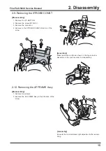
Страница 15: ...r 2 Remove in the STROBE CONST direction of the arrow 1 2 3 4 Assembly Make read wire a style as shown in the figure below Assemble in the reverse order to disassembly 2 10 Removing the AF FRAME Assy Disassembly 1 Remove two screws 2 Remove the AF FRAME Assy in the direction of the arrow 1 2 Assembly Execute the AF assistance light adjustment after assem bling ...

Страница 16: ... not displayed 3 2 Basic Block Names and Functions Part name Block name Function LENS CONST CCD BLOCK CCD output MAIN PWB ASSY CAMERA BLOCK CCD output A D conversion IC103 CCD driver IC101 IC102 PROCESS BLOCK Image signal processing USB communications system control IC206 LCD EVF BLOCK LCD EVF output control IC401 AUDIO BLOCK Audio IN OUT IC11 DCST PWB ASSY DC DC BLOCK Power supply generation IC50...

Страница 17: ...calculations by the auto calculation unit and sent to the ACS IC103 CCD processing IC of the CAMERA BLOCK so as to obtain a suitable AE AWB and AF Recording to the xD picture card The image data stored in the IC204 IC205 DRAM 128 Mbit of the system LSI UCS2 IC206 is sent to the signal processing block one line at a time where it undergoes unpack processing processing required prior to digital clam...

Страница 18: ...Focus Iris Zoom Pulse 1 5V 3 3V 5v CCD16V 8V LCD805V Etc Detect system VRESET OCONT STRB CONT Video Driver CCD_ON PWON_ACT RESET STRB_FULL STRB_COK STRB_CC STRB_SY LED BEEP VIDEO_ON VBS_OUT EVF BL EVF 0 33inch AV Jack MODE SW MODE DIAL DRIVE SW LED SELF TIMER FOCUS SW AF MF CAF SW POPUP SW SIO_1 U2_SIO IST GS1 GS2 END S S CP Digital Gain Gray Code 10xZOOM LENS f 5 8 58 0mm F 2 8 3 1 O LPF HA CCD M...

Страница 19: ...CK 36 GND 37 MOT_CS 38 MOT_CLK 39 CCD_ON 40 MOT_MOB_Z 41 MOT_ON 42 MOT_MOB_F 43 MOT_EXT 44 MOT_MOB_I 45 UNREG 46 D 47 GND 48 D 49 GND 50 VBUS 51 STRB_COK 52 STRB_SY 53 STRB_CC 54 FULL 55 STRB_CHG 56 GND 57 G_SEL 58 GND 59 G_ON 60 1 GND 2 AD_2 5V 3 S1 4 S2 5 PLAY 6 EV3 7 PW_SW 8 GND GND 1 AD_2 5V 2 S1 3 S2 4 PLAY 5 EV3 6 PW_SW 7 GND 8 1 GND 2 AD_2 5V 3 R L D U 4 T W F 5 OK B D E_L 6 D_3 3V 7 LED_G ...

Страница 20: ...20 3 Schematics FinePix S5000 Service Manual 3 6 CCD BLOCK Schematic Diagram ...

Страница 21: ...21 FinePix S5000 Service Manual 3 Schematics 3 7 CAMERA BLOCK Schematic Diagram ...

Страница 22: ...22 FinePix S5000 Service Manual 3 Schematics 3 8 PROCESS BLOCK Schematic Diagram ...

Страница 23: ...23 3 Schematics FinePix S5000 Service Manual 3 9 POWER BLOCK Schematic Diagram ...

Страница 24: ...24 3 Schematics FinePix S5000 Service Manual 3 10 LCD EVF BLOCK Schematic Diagram ...

Страница 25: ...25 3 Schematics FinePix S5000 Service Manual 3 11 F SW BLOCK Schematic Diagram 3 12 M SW BLOCK Schematic Diagram ...

Страница 26: ...26 3 Schematics FinePix S5000 Service Manual 3 13 KEY SW BLOCK Schematic Diagram ...

Страница 27: ...27 3 Schematics FinePix S5000 Service Manual 3 14 MOTOR BLOCK Schematic Diagram ...

Страница 28: ...28 3 Schematics FinePix S5000 Service Manual 3 15 POWER ON BLOCK Schematic Diagram ...

Страница 29: ...29 3 Schematics FinePix S5000 Service Manual 3 16 FLASH BLOCK Schematic Diagram ...

Страница 30: ...30 3 Schematics FinePix S5000 Service Manual 3 17 R SW BLOCK Schematic Diagram ...

Страница 31: ...31 3 Schematics FinePix S5000 Service Manual 3 18 CCD FPC ASSY Component Locations Side A Side B 3 19 RSW PWB ASSY Component Locations Side A Side B ...

Страница 32: ...32 3 Schematics FinePix S5000 Service Manual 3 20 MAIN PWB ASSY Component Locations Side A Side B ...

Страница 33: ...33 3 Schematics FinePix S5000 Service Manual 3 21 DCST PWB ASSY Component Locations Side A Side B ...

Страница 34: ...34 3 Schematics FinePix S5000 Service Manual 3 22 KSW PWB ASSY Component Locations Side A Side B ...

Страница 35: ...35 3 Schematics FinePix S5000 Service Manual 3 23 MSW PWB ASSY Component Locations Side A Side B ...

Страница 36: ... 100 AF Assist Light adjustment 1 Conversion lens f 1560 69mm ZJ00734 100 AF adjustment Conversion lens f 865 12mm ZJ00735 100 AF adjustment Lens holder 70mm ZJ00736 100 AF adjustment Stand ZJ00009 100 AF adjustment common to 8mm VTR FinePix 500 Base plate ZJ00010 100 AF adjustment common to 8mm VTR FinePix 500 Grey chart reflective ZJ00254 100 Strobe adjustment common to FinePix 700 USB cable FZ0...

Страница 37: ...nolta Color Meter III F or equiva lent Color temperature measurement Filter LB140 and pattern box in direct contact Adjust color temperature of pattern box to 6100 50K with filter LB140 in contact with color thermometer 2 Luminance 160 5cd m2 with LB140 filter Measurement position middle of pattern box Measuring device Minolta Luminance Meter LS 110 or equivalent Luminance measurement Filter LB140...

Страница 38: ...y influenced by external light The periphery of the gray chart should therefore be as dark as possible to minimize this influence Ensure that the gray chart is at a distance of 1000mm from the camera reference face 1 Use a Superior Oxford Gray No 22 chart or a chart with reflectivity of 18 0 7 Conversion lens Distance A 1560 69mm 25 16mm 865 12mm 30 64mm 932mm 2mm Line chart Fluorescent light stan...

Страница 39: ..._ S5000_W adjustment software media ZJ00674 100 in the drive on the PC Step 2 Copy each of the folders in the FinePix_S5000_W folder to the C drive on the PC Fig E Step 3 When all the folders have been copied to the C drive double click on C FinePix_S5000_W FFW exe Fig E to start Fig D 4 6 Installing the Jig Drivers on the PC As this device uses a USB interface for communica tions with the PC the ...

Страница 40: ...llows Fig I 2 Item Details of automatic measure 0 Permit mode change Do t check Use Japanese font Do t check Don t show OK NG Check or Don t check Note If Disable OKNG display on the PC screen Fig H is set to OFF the PC screen displays OK if adjustment is OK and NG if adjustment is NG either setting is OK Step 5 Select the Hardware menu on the Customize dialog screen Fig J 1 Input the data to each...

Страница 41: ...User program help FOCAS Do not use with adjustment software Version Basic software version information Cautions for Adjustment Caution 1 Running End setting returns the camera to the Product mode from the Jig mode Always run End setting if the PC adjust ment software has been used to operate the camera End setting is not run the camera will be recognized as Mass Storage when con nected to the PC a...

Страница 42: ... to display the adjustment software start up screen Fig 1 Run the adjustment in accordance with the instructions on the screen Fig 2 The FFW exe Start up Screen Fig 1 window appears Step 2 Press the Enter key or the Start button Fig 1 1 Fig 1 Inithal Screen Fig 2 appears Step 3 Press the Enter key after checking when using the adjustment software 1 ...

Страница 43: ...l The Jig Mode Setup Procedure Screen Fig 3 appears Step 4 Set the camera in the Jig mode and press the Enter key The Firmware Display Screen Fig 4 appears Firmware Confirmation Screen Step 5 Press the Enter key Fig 4 Fig 3 Run the adjustment in ...

Страница 44: ...ion AF Asasist light adjustment Press the F 9 key CCD data input Press the F 4 key Camera adjustment Press the F 5 key AF adjustment Press the F 6 key Battery voltage adjustment Press the F 1 key Flash adjustment Press the F 7 key VIDEO adjustment Press the F11 key Firmware download Press the F 8 key End setting Press the F12 key Fig 5 ...

Страница 45: ... Preparation for AF Assist Light adjustment 1 Output the image to TV with a camera that works normally 2 Apply the sign according to the mark of the center of the AF target 3 Remove Cabinet R and tighten one screw 932mm 2mm Line chart Fluorescent light stand Camera Center Setup for AF Assist Light adjustment TV Center Lighting image 1mm Monitor TV Picture ...

Страница 46: ... AF Assist light adjustment Preparation Screen Fig 6 appears Step 2 When preparations are complete press the Enter key The AF Assist light adjustment Preparation Screen Fig 7 appears Step 3 When preparations are complete press the Enter key Fig 6 Fig 7 Caution When adjusting the camera measure distance from the front face of the camera lens ...

Страница 47: ...o that the irradiation standard of the AF assist light may enter in a specified area Step 4 When preparations are complete press the Enter key The AF Assist light adjustment complete Screen Fig 9 appears Step 5 Press the Enter key while in the AF Assist light adjustment Complete Screen Fig 9 The system returns to the Adjustment Items Select Screen Fig 5 ...

Страница 48: ... discarded and 2 to5 digits are used The four digits from the top in the second line are then appended to form the CCD data file name Record this file name Cautions 1 The CCD damage data file extension is dat Depending upon Windows settings this extension may not be displayed In this case change the settings to ensure that it is displayed 2 In addition to numbers letters are also used in the CCD s...

Страница 49: ...entered 3 Insert the CCD data floppy disk in the floppy disk drive A drive When preparations are complete press the Enter key Click on the OK button CCD Data input begins When adjustment is completed satisfactorily write the adjustment data to the Flash_ROM When the adjustment data is written satisfactorily to the Flash ROM the CCD Data Input Complete Screen Fig 12 appears Step 8 Press the Enter k...

Страница 50: ...level adjustment Step 1 Select F5 from the Adjustment Items Select Screen Fig 5 press F5 on the PC keyboard The Shutter Adjustment Preparation Screen Fig 13 appears Caution When adjusting the camera measure distance from the front face of the camera lens Step 2 When preparations are complete press the Enter key Camera adjustment begins Run the adjustment in accordance with the instructions on the ...

Страница 51: ...s on the screen Fig 15 When preparations are complete press the Enter key Camera adjustment moves to the next stage Step 4 Remove the LB140 filter in accordance with the instructions on the screen Fig 16 When preparations are complete press the Enter key Camera adjustment moves to the next stage Fig 15 Fig 16 ...

Страница 52: ...ix S5000 Service Manual Step 5 The screen in Fig 17 appears when adjustment is completed satisfactorily Press the Enter key The system returns to the Adjustment Items Select Screen Fig 5 Camera adjustment is completed Fig 17 ...

Страница 53: ... After replacing the LENS CONST or MAIN PWB ASSY always run AF adjustment after camera adjustment 3 Do not conect VIDEO cable while adjusting AF Step 1 Select F6 from the Adjustment Items Select Screen Fig 5 press F6 on the key board The AF Adjustment Preparation Screen Fig 18 appears Step 2 When preparations are complete press the Enter key Fig 18 Run the adjustment in accordance with the instruc...

Страница 54: ...ervice Manual The AF Adjustment Start screen Fig19 appears Step 3 When preparations are complete press the Enter key The AF 2000mm Adjustment screen Fig20 appears Fig 19 Fig 20 Step 4 When preparations are complete press the Enter key ...

Страница 55: ...Step 5 When preparations are complete press the Enter key Adjustment proceeds to backlash adjustment zoom reset adjustment and AF adjustment and the AF Adjustment Complete Screen Fig 22 appears Step 6 Press the Enter key The system returns to the Adjustment Items Select Screen Fig 5 AF adjustment is now complete ...

Страница 56: ...y result in interruption of communication between the adjustment software and the camera and the adjustment software may produce an error Restart the adjustment software in this case Step 1 1 Connect as shown in the connection diagram Run the adjustment in accordance with the instructions on the screen 2 Place the camera lens upwards as the lens will operate care is required When preparations are ...

Страница 57: ...tage Setting Screen 2 15V Fig 24 appears Step 3 Set input voltage battery preend voltage adjustment and press the Enter key The Battery Voltage Setting Screen 2 05V Fig 25 appears Step 4 Set input voltage at battery end voltage adjustment and press the Enter key Fig 25 ...

Страница 58: ... Screen 3 00V Fig 26 appears Step 5 Set input voltage at 3 00V and press the Enter key Fig 26 The Battery Voltage Setting Complete Screen Fig 27 appears Step 6 Press the Enter key The system returns to the Adjustment Items Select Screen Fig 5 Battery voltage adjustment is completed ...

Страница 59: ...is influence 2 When adjusting the flash measure distance from the front of the camera body 3 Always run flash adjustment after completing CAMERA adjustment Step 1 Select F7 from the Adjustment Items Select Screen Fig 5 press the F7 key on the keyboard Run the adjustment in accordance with the instructions on the screen The Flash Adjustment Preparation Screen Fig 28 appears Step 2 When preparations...

Страница 60: ...tment start Screen Fig 29 appears Step 3 When preparations are complete press the Enter key The Flash Adjustment Complete Screen Fig 30 appears Step 4 Press the Enter key The system returns to the Adjustment Items Select Screen Fig 5 Flash adjustment is complete Fig 30 ...

Страница 61: ...tart the camera before adjustment Step 1 1 Connect as shown in the connection diagram Select F11 VIDEO Adjustment on the Adjustment Items Select screen Fig 5 The VIDEO Adjustment Preparation screen Fig 32 appears Step 2 When preparations are complete press the Enter key Run the adjustment in accordance with the instructions on the screen AC 100 240V To PCI 2746C Board VIDEO ADJ JIG USB CABLE POWER...

Страница 62: ...ments FinePix S5000 Service Manual The VIDEO Adjustment Complete screen Fig 33 appears Step 3 Press the Enter key The system returns to the Adjustment Items Select Screen Fig 5 VIDEO adjustment is completed Fig 33 ...

Страница 63: ...ig mode and checking on the displayed Firmware Version Check Screen Fig 4 Step 1 Select F8 from the Adjustment Items Select Screen Fig 5 press the F8 key on the keyboard The Download start Screen Fig 34 appears Step 2 Follow the instructions on the Download start Screen Fig 28 and press the Enter key The Downloading Screen Fig 35 appears Fig 35 ...

Страница 64: ...the new firmware when power is switched OFF ON Step 4 The Jig Mode Setup Screen Fig 2 set the camera in the jig mode and press the Enter key twice The Firmware Version Check Screen Fig 4 appears this screen displays the upgraded version Step 5 Press the enter key while in the Firmware Version Check Screen Fig 4 The Adjustment Items Select Screen Fig 5 appears Step 7 Select another adjustment item ...

Страница 65: ...le PC the PC will be unable to identify each USB device thus preventing operation Step 1 Select F12 from Adjustment item Select Screen Fig 5 ie press the F12 key on the computer The End Setting Start Screen Fig 37 is appears Step 2 Follow instructions on the End Setting Start Screen Fig 31 and press the Enter key Numbers in indicate decimal numbers Other numbers are ASCII numbers 2 Automatically w...

Страница 66: ... third character from left side of the serial number shows the destination Select it according to the destination Press the B key to select US CA model Press the Enter key This example uses Destination B as the US CA model Step 3 The Destination Selected Screen Fig 39 is appears Press the Enter key Fig 39 ...

Страница 67: ...5000 Service Manual Fig 40 Step 4 Follow instruction on the Repair site Select Screen Fig 40 and press the H key This example uses USA site Fig 41 The USB ID USA site selected Screen Fig 41 is appears Step 5 Press the Enter key ...

Страница 68: ...the Product Mode Setting Screen Fig 42 When the settings are completed normally they are saved to the flash ROM and the FinePix S5000 Adjustment finished Screen Fig 43 is appears Step 8 1 Remove jig and all cables from the camera 2 Press the Enter key on the PC The display returns to the Inithal Screen Fig 2 after pressing the Enter key Fig 42 Fig 43 ...

Страница 69: ...1 Place battery in camera 2 Insert card and close card cover 3 Set mode dial to still photography mode 4 Turn power ON 5 If the date set message appears press Cancel 1 Apply an appropriate shock to the camera Do not apply shock directly to the lens or card cover 1 Macro photography distance approximately 10 80cm 2 Press shutter button to take photographs No problem with click action of switches No...

Страница 70: ...er Beep LOW Language Engrish Pixels 1M normal Photography mode AUTO Date Not set 3 Inspection battery inspection xD Picture card not inserted in camera 4 Battery cover closed 5 LCD surface free of contamination 6 Clean exterior of camera 1 Standby display on LCD 2 Movie recording begins Recording displayed on LCD 3 Movie recording completed Recording on card 2 Movie played back on LCD monitor 1 Sw...

Страница 71: ...A104 BB12943 100 BAR CODE LABEL BLANK A105 AZF0000 311 HDPE BAG NO 11 A106 FZ04793 100 ALKALINE BATTERY A107 FZ04741 100 WIRE HARNESS A108 FZ05241 100 WIRE HARNESS USB A109 BU02939 100 SHOULDER BELT ASSY A110 BU02876 100 LENS CAP ASSY A111 BU02875 100 LENS HOOD ASSY A112 AZF0000 101 LDPE BAG NO 10 A113 BL00260 200 MANUAL S5000 ENG A114 BB07792 101 WARRANTY US A115 BB03538 100 IMPORTANT SAFETY A116...

Страница 72: ...0 BAR CODE LABEL BLANK A105 AZF0000 311 HDPE BAG NO 11 A106 FZ04793 100 ALKALINE BATTERY A107 FZ04741 100 WIRE HARNESS A108 FZ05241 100 WIRE HARNESS USB A109 BU02939 100 SHOULDER BELT ASSY A110 BU02876 100 LENS CAP ASSY A111 BU02875 100 LENS HOOD ASSY A112 AZF0000 101 LDPE BAG NO 10 A113 BL00260 200 MANUAL S5000 ENG A114 BL00260 300 MANUAL S5000 FRE A115 BL00261 100 QUICK MANUAL S5000E A116 BL0026...

Страница 73: ...AG NO 11 A106 FZ04793 100 ALKALINE BATTERY A107 FZ04741 100 WIRE HARNESS A108 FZ05241 100 WIRE HARNESS USB A109 BU02939 100 SHOULDER BELT ASSY A110 BU02876 100 LENS CAP ASSY A111 BU02875 100 LENS HOOD ASSY A112 AZF0000 111 BAG PLASTIC NO 11 A113 BL00260 200 MANUAL S5000 ENG A114 BL00260 300 MANUAL S5000 FRE A115 BL00260 400 MANUAL S5000 GER A116 BL00261 100 QUICK MANUAL S5000E A117 BL00261 200 QUI...

Страница 74: ... A104 BB12943 100 BAR CODE LABEL BLANK A105 AZF0000 311 HDPE BAG NO 11 A106 FZ04793 100 ALKALINE BATTERY A107 FZ04741 100 WIRE HARNESS A108 FZ05241 100 WIRE HARNESS USB A109 BU02939 100 SHOULDER BELT ASSY A110 BU02876 100 LENS CAP ASSY A111 BU02875 100 LENS HOOD ASSY A112 AZF0000 101 LDPE BAG NO 10 A113 BL00260 200 MANUAL S5000 ENG A114 BL00176 100 H14 WARRANTY CARD EG A115 BL00261 100 QUICK MANUA...

Страница 75: ...00 PARTITION PAD A104 BB12943 100 BAR CODE LABEL BLANK A105 AZF0000 311 HDPE BAG NO 11 A106 FZ04793 100 ALKALINE BATTERY A107 FZ04741 100 WIRE HARNESS A108 FZ05241 100 WIRE HARNESS USB A109 BU02939 100 SHOULDER BELT ASSY A110 BU02876 100 LENS CAP ASSY A111 BU02875 100 LENS HOOD ASSY A112 AZF0000 101 LDPE BAG NO 10 A113 BL00260 400 MANUAL S5000 GER A114 BL00261 300 QUICK MANUAL S5000G A115 BF04146 ...

Страница 76: ...00 PARTITION PAD A104 BB12943 100 BAR CODE LABEL BLANK A105 AZF0000 311 HDPE BAG NO 11 A106 FZ04793 100 ALKALINE BATTERY A107 FZ04741 100 WIRE HARNESS A108 FZ05241 100 WIRE HARNESS USB A109 BU02939 100 SHOULDER BELT ASSY A110 BU02876 100 LENS CAP ASSY A111 BU02875 100 LENS HOOD ASSY A112 AZF0000 101 LDPE BAG NO 10 A113 BL00260 200 MANUAL S5000 ENG A114 BL00261 100 QUICK MANUAL S5000E A115 BF04146 ...

Страница 77: ...205 BB16942 100 MIC SHEET M206 FZ04998 100 MIC ASSY M207 FZ04224 100 SPEAKER ASSY M208 BB16856 100 SP SHEET M209 FZ05547 100 AF FRAME ASSY M210 BB16693 100 ADJUSTMENT SPRING M211 BB16695 100 ADJUSTMENT SCREW M212 BU02940 100 STROBE CONST M213 FZ05545 100 FSW PWB ASSY M214 FZ05436 100 FFC M215 FZ05542 100 ST PWB ASSY M216 FZ05413 100 LIGHT M217 BB16362 100 ST TOP M218 BB16365 100 FLASH COVER M219 A...

Страница 78: ...18 A300 RSW PWB ASSY M315 BF04549 100 LENS CONST WITH DATA M316 FZ05317 100 LENS UNIT M317 FZ05214 100 OPTICAL LPF M318 BB14921 100 LPF RUBBER M319 BB16353 100 LPF MASK M320 BB16332 100 CCD PLATE M321 ATG1713 0NN BT1P17 30N M322 CB1119 A101 CCD PWB ASSY M323 BB16939 100 CCD EMI SHEET L M324 BB16940 100 CCD EMI SHEET R M325 BB16963 100 EMI CCD F SHEET M326 BB16951 100 MF SHEET2 M327 BB16941 100 MF ...

Страница 79: ...16943 100 K SHEET M403 BB17025 100 CONTACT SHEET B M404 CB1118 A200 MSW PWB ASSY M405 ATG1724 0ND SCREW M406 FZ05434 100 FFC M407 BU02871 100 CABI REAR ASSY M408 BB16374 100 CARD COVER M409 BB16413 100 CARD COVER SHAFT M410 BB16823 100 ZOOM KEY M411 BB16375 100 OPERATION BUTTON M412 BB16378 100 F BUTTON M413 BB16740 100 LCD CUSHION M414 BB16832 100 W FACE LCD COVER M415 BB13148 100 BL SCREW M1 7X3...

Страница 80: ...CAP LA 190MF 350V K 13 2 F501 FP00039 253 FUSE 2 5A 32V UL F502 FP00018 253 FUSE2 5A 125V JIS F503 FP00039 253 FUSE 2 5A 32V UL F504 FP00039 253 FUSE 2 5A 32V UL F505 FP00039 153 FUSE 1 5A 32V UL F506 FP00039 502 FUSE500MA 32V UL CN501 FGA113 0021 CONNECTOR CJ 2PRN1 5MM PH CN502 FZ05344 100 JACKUSB MINI B CN503 FGC143 0601 CONNECTOR CJ60PBN0 5MMRV CN601 FGA058 0021 CONNECTOR CJ2PRN1 25MMPN CN602 F...

Страница 81: ...anual 7 Appendix 7 1 List of Related Technical Updates Issued To ensure that after sales srevice is performed accuratety keep a record here of the technical updates issued that cover this device Technical Update No Date Title Details Other ...

Страница 82: ...26 30 Nishiazabu 2 chome Minato ku Tokyo 106 8620 Japan FUJI PHOTO FILM CO LTD ...

Отзывы: