11
M2
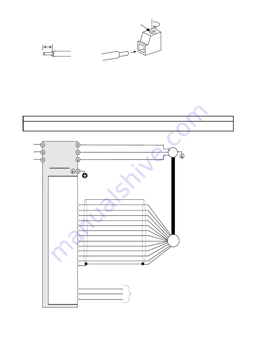
4.3 Basic Wiring Diagram
CAUTION
•
Keep the power supply voltage of encoder in the specification voltage of encoder.
There is a risk of failure.
L1/R
L2/S
L3/T
U
V
W
M
CK-
DT+
DT-
FRN-LM1S
G
OPC-LM1-PS1
PA-
PB+
PB-
CK+
PO
PA+
PO
CM
CM
Encoder
FPA
FPB
CM
CM
User
Controller
Figure 4.1 Basic Wiring Diagram
7(mm)
Connection of Wiring on Option
Terminal Side.


