


9
3 Applicable Encoder
CAUTION
•
Check the encoder specification again before operating the inverter. Improper encoder specification may cause
unexpected inverter operation or device operation.
There is a risk of accident or injury.
3.1 Specifications of Applicable Encoder
Table 3.1 Specifications of Applicable Encoder
Item Specifications
Incremental signals
2 sinusoidal signals A and B as sine and cosine with 2048 periods per
revolution
Rotor Position Detection
2 sinusoidal signals C and D as sine and cosine with one period per revolution
+5 VDC (5 VDC ±5%/300 mA)
Application
encoder
Encoder power supply
Encoder model
HEIDENHAIN ECN1313 or its equivalent
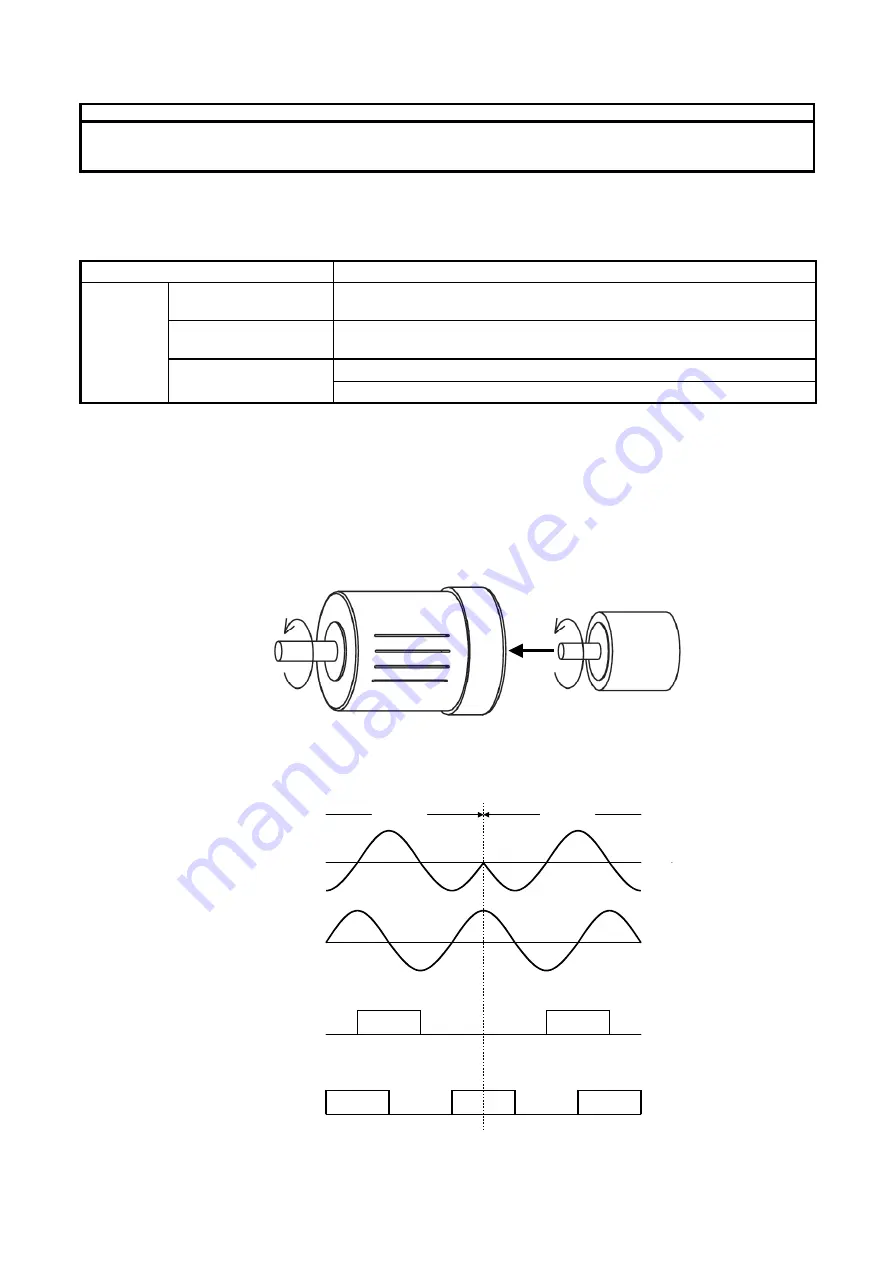
3.2 Encoder Installation and Signal
The encoder shall rotate in the direction shown in Figure 3.1 when terminal FWD is ON.
Encoder output pulse is shown in Figure 3.2. Connect the encoder directly to the motor using a coupling.
If the encoder rotation is different from that shown in Figure 3.1, interchange V with W of inverter output.
The rotational direction of IEC standard motors is opposite to that shown in Figure 3.1.
Motor
Encoder
Rotational direction when terminal FWD is ON.
Driving side
Figure 3.1 Motor and Encoder Rotational Direction when Terminal
FWD is ON
FWD ON
REV ON
FPA
FPB
PA+,PA-Differential
input signal
PB+,PB-Differential
input signal
Figure 3.2 Definition of Terminal FWD ON/REV ON


