CAP-600
30
INSPECTION & MAINTENANCE OF
E-57 VALVE ASSEMBLY
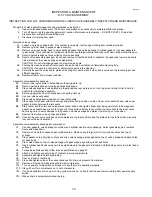
INSTRUCTION FOR E-57 COMPRESSOR MODEL HEAD VALVE ASSEMBLY INSPECTION AND MAINTENANCE.
Model E-57 valve assembly inspection and maintenance instruction.
1. Inspect valve assemblies every 1000 hours of operation or as necessary to maintain efficient operation.
2. Turn off power, red tag power supply switch (caution: Maintenance in progress – DO NOT START). Drain all air
pressure from system before starting work.
3. Disconnect air piping from head.
Remove valve package.
A1. Loosen and remove head bolts. On constant run models, remove upper tubing from unloader cylinder.
A2. Remove cylinder head to expose valve assembly.
A3. Remove valve assembly, head to valve package gasket and valve package to cylinder gasket. Use new gaskets in
re-assembly. Note conditions of cylinders, clean out any foreign material and cover with clean shop cloth while open.
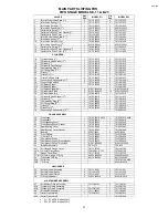
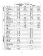
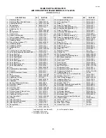
A4. Refer to parts breakdown for description of valve package.
A5. Secure valve assembly package, loosen and remove socket head bolts to separate the upper and lower valve seats.
This will expose the valve springs and valve plates.
CAUTION: Do not interchange upper and lower valve seats
A6. Thoroughly clean and wash all valve seats and parts with a suitable non-flammable cleaning fluid.
CAUTION: Use care to not scratch or deform valve parts in the cleaning.
A7. Carefully inspect the valve seats, plates and springs for dents, cracks, wear, and any reason to prevent proper and
efficient
operation.
A8. Replace all parts not in proper condition.
Assemble valve assembly package.
B1.
Secure lower valve plate in flat position with spring slots “up”.
B2.
Refer to parts breakdown for valve package breakdown.
B3.
Place valve springs and valve plates in proper positions over slots in seat. Use tag wire or string for tie to hold in
position for completing assembly.
B4.
Secure upper valve seat in flat position with spring slots up
B5.
Use new valve seat gasket.
B6.
Place valve seat gasket in position on lower valve plate.
B7.
Place upper valve seat with valve springs and plates tied in position on top of lower valve seat with new valve seat
gasket in place between the two seats.
B8.
Start center and then two end valve plates socket head bolts, tighten finger tight being careful not to damage seat
gasket, use socket head wrench to torque the three bolts uniformly to secure the top valve seat to the lower valve
seat using care to avoid damage to the gasket, and valve springs and plates from moving out of position.
B9.
Remove ties to free valve springs and plates
B10. Check to be sure valve springs and valve plates are in proper position and the plates are free to flex when manually
touched with blunt instrument.
Assemble valve assembly package into compressor.
C1.
Use new gaskets, valve package to cylinder and cylinder head to valve package. Select gaskets by part numbers
from parts breakdown.
C2.
Remove shop cloth to expose open cylinder bores. Remove any foreign matter from cylinder bores and top of
cylinder.
C3.
Place gasket on top of cylinder, place and align valve package, place gasket on top of valve package and align holes
for head bolts.
C4.
Place clean head on top of valve package with gasket and align with cylinder bolt holes.
C5.
Insert cylinder head bolts using care to avoid damage to the gaskets, start each bolt threading evenly to contact head
surfaces.
C6.
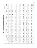
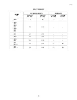
Torque head bolts equally, follow torque specifications on page 20.
C7.
Attach and tighten copper tubing of constant running compressors.
C8.
Assemble and tighten discharge tubing.
C9.
Check oil level in crankcase
C10. Close and tighten valve or the connections used to drain air pressure from system.
C11. Remove all tools and make area safe to start compressor.
C12. Turn on power at main switch and inspect to see that unit is operating properly.
C13. Stay with unit for normal pump up to cut out pressure.
C14. If unit has performed through a running cycle properly put on line for duties and remove red tag from power supply
switch.
C15. Make entry in equipment maintenance log.
Содержание CA series
Страница 12: ...CAP 600 12 AIR COOLED SINGLE STAGE MODELS ES 05 ES 10 ES 20 ...
Страница 20: ...CAP 600 AIR COOLED SINGLE STAGE MODEL ES 150A 18 ...
Страница 22: ...CAP 600 AIR COOLED SINGLE STAGE MODEL ES 150B 18A ...
Страница 24: ...CAP 600 20 AIR COOLED TWO STAGE MODELS E 11 E 23 ...
Страница 30: ...CAP 600 AIR COOLED TWO STAGE MODEL E 25 25A ...
Страница 34: ...CAP 600 26 AIR COOLED TWO STAGE MODEL E 35 ...
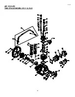
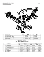
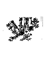
Страница 36: ...AIR COOLED TWO STAGE MODEL E 57 E57A CAP600 28 ...
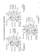
Страница 39: ...CAP 600 31 VALVE PLATES DESIGNS FOR E 57 COMPRESSOR ...
Страница 47: ...CAP 600 NOTES 39 ...

