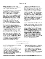
CAP-600
4
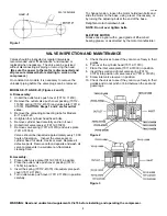
Figure 1
To change tension, loosen the motor hold-down bolts and
slide the motor on the base, using a lever if necessary, or
by turning the adjusting bolt at the end of the base.
Retighten motor hold-down bolts.
NOTE: Do not over tighten belts.
ELECTRIC MOTOR
Grease once a year with a good grade of lithium ball
bearing grease, or as directed by the motor manufacturer.
VALVE INSPECTION AND MAINTENANCE
Valves should be inspected at regular intervals as
recommended under "Maintenance" and cleaned or
replaced when necessary. The valve can be serviced
without disconnecting air piping or removing the head.
(Be sure the power to the motor is disconnected and
all pressure released before starting to work on the
compressor.)
On constant run models, it is necessary to remove the
unloader piping before the valve plugs can be removed.
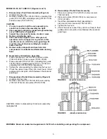
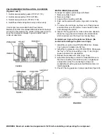
MODELS E-11 AND E-23 (Figures 2 and 3)
A. Disassembly:
1. Unbolt the outlet valve push cover (70112- 11450).
2. Remove the outlet valve push cover packing (70112-
11650), spring (70112-41070) and valve plate (70112-
31030).
CAUTION: Steps 1 and 2 are for outlet
valve.
3. Remove the unloading connecting tube for Models
E-11 and E-23.
4. Untighten four cylinder head fixed bolts.
5. Remove cylinder head carefully and turn it over.
6. Unbolt inlet valve receiver (70112-31020).
7. Remove valve spring (70112-31070) and valve plate
(70112-31030).
Valves should be inspected approximately every 1,000
hours of operation. Inspect the valve seats on
cylinder head for dents, cracks or wear. Replace all
defective parts. Remove carbon deposits and wash all
valve components in a suitable non-flammable
cleaning fluid.
B. Assembly:
1. Place outlet valve plate (70112-31030) in position.
2. Place the outlet valve push cover packing (70112-
11650) in position.
3. Insert the spring (70112-41070) into outlet valve push
cover (70112-11450).
4. Turn outlet valve push cover (70112-11450) in position
carefully.
5. Check the valves to see if they can move freely in their
guides.
6. Turn over the cylinder head (70112-11010).
7. Place the inlet valve plate (70112-31030) in position.
8. Insert the small end of inlet valve spring (70112-
31070) into position of valve receiver (70112- 31020).
9. Screw inlet valve receiver in position.
10. Check the valves to see if they can move freely in their
guides and do not pinch or bind between the seat and
guard legs.
Figure 2
Figure 3
WARNING: Read and understand supplement LV-474 before installing and operating the compressor.
Содержание CA series
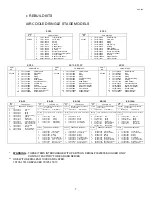
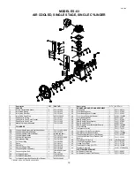
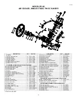
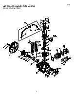
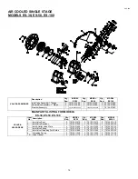
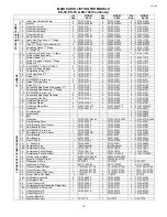
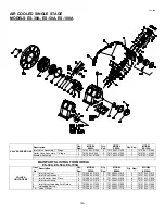
Страница 12: ...CAP 600 12 AIR COOLED SINGLE STAGE MODELS ES 05 ES 10 ES 20 ...
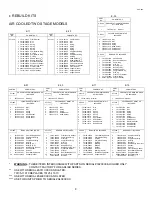
Страница 20: ...CAP 600 AIR COOLED SINGLE STAGE MODEL ES 150A 18 ...
Страница 22: ...CAP 600 AIR COOLED SINGLE STAGE MODEL ES 150B 18A ...
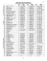
Страница 24: ...CAP 600 20 AIR COOLED TWO STAGE MODELS E 11 E 23 ...
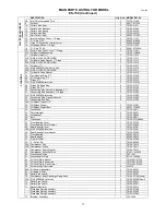
Страница 30: ...CAP 600 AIR COOLED TWO STAGE MODEL E 25 25A ...
Страница 34: ...CAP 600 26 AIR COOLED TWO STAGE MODEL E 35 ...
Страница 36: ...AIR COOLED TWO STAGE MODEL E 57 E57A CAP600 28 ...
Страница 39: ...CAP 600 31 VALVE PLATES DESIGNS FOR E 57 COMPRESSOR ...
Страница 47: ...CAP 600 NOTES 39 ...


