background image

CAP-600 


10

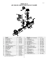
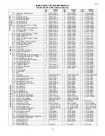
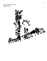
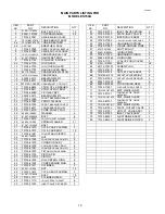
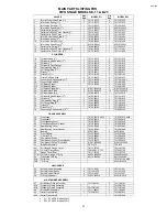
MODEL ES-03 

AIR COOLED, SINGLE STAGE, SINGLE CYLINDER 


 Description 

QTY 

PART 

NO. 

 VALVES 


1. 

Inlet  & Outlet Valve Plate 

70111-31030 

2. 

Inlet Valve Spring 

70111-31070 

3. 

Inlet Valve Receiver 

70111-31020 

4. 

Inlet Valve Snap Ring 

93610-130225 

5. Outlet 

Valve 

Spring 

1 70111-41070 

6. 

Outlet Valve Push Cover Gasket 

70111-11461 

7. 

Outlet Valve Push Cover 

70111-11450 

8. 

Manual Unloader Assembly 

70111-11300 

9.  


CYLINDERS 


9A. 

Cylinder Head Assembly (Includes Valves) 

70111-11000-4024 

9B. 

Cylinder Head (Bare Casting) 

70111-11010 

10. 

Cylinder Head Bolt (Not Shown) 4 

(Hardware 

Item) 

11. Cylinder 

Head 

Gasket 

1  70111-11612 

12. 

Cylinder & Crankcase 

70111-57010-4024 

13. Compression 

Ring 

2  70111-61030 

14. 

Oil Control Ring 

70111-61050 

15. Piston 

1  70111-61011 

16. Piston 

Pin 

1  70111-61120 

17. 

Piston Pin Snap Ring 

70111-61070 

18. 

Connecting Rod Assembly 

70111-61200 

19. 

Connecting Rod Bolt 

(furnished on conn. 
Rod only) 

20. 

Oil Splash Dipper 

70111-61282 

21. 

Oil Splash Dipper Bolt 

91507-2304010 

22. 

Oil Splash Dipper Bolt Washer (Not Shown) 

92522-130400 


Description 

QTY PART 

NO. 


CRANKCASE AND CRANK ASSEMBLY 


23. Crankshaft 

1  70111-56010 

24. 

Front Bearing Cover 

70111-57030 

25. 

Front Bearing Cover Gasket 

70111-57950 

26. 

Front Cover Bolts (Not Shown) 

91501-1306016 

27. 

Front Bearing #6203 

93501-6203 

28. 

Rear Bearing Cover 

70111-57060 

29. 

Rear Bearing Cover Gasket 

70111-57960 

30. 

Rear Bearing #6201 

93501-6201 

31. 

Rear Bearing Cover Bolts (Not Shown) 

93501-1306016 

32. Front 

Oil 

Seal 

1  70111-57080 

33. Compressor 

Pulley 

1  70111-76010 

34. 

Compressor Pulley Thrust Washer 

70111-76210 

35. 

Compressor Pulley Thrust Bolt 

91501-1306020 

36. 

Crankcase Bottom Cover (Not Shown) 

70111-57220 

37. 

Crankcase Bottom Cover Gasket (Not 
Shown) 

1 70111-57970 

38. 

Compressor Pulley Pin 

NA 

(Not Required) 

39. 

Oil Level Gauge And Cover 

70111-57700 

40. 

Gauge Cover Seal 

70111-57730 

41. 

Crankcase Oil Plug (1/4” PT) 

90112-100202 

42. Breather 

Assembly 

1  70191-57600-4024 


AIR STRAINER ELEMENT 


43. 

Air Strainer Assembly 

70111-66001 

44. 

Air Strainer Element (Not Shown) 

70111-66140 

CRANKCASE AND CRANK ASSEMBLY


Содержание CA series

Страница 1: ...talling and operating this compressor read and understand the safety precautions contained in LV 474 supplement to and part of CAP 600 IMPORTANT Make a permanent record of the Model and Serial number of your machine here You ll save time and expense by including this reference identification on replacement part orders BY PERFORMANCE DATA SHEET REFER TOMODEL SERIAL NUMBER R P M OR ABOVE MAX AS STIP...

Страница 2: ...provide a safety relief valve in the discharge line between the compressor and in line shutoff valves If more than one compressor pumps into a common system a check valve in the discharge line of each compressor is recommended to prevent moisture from entering the cylinder head when one compressor is idle A globe or gate valve installed in the discharge line will allow compressor isolation from pl...

Страница 3: ...P M recommended for the various models 2 Maintain oil level mid way between the upper and lower lines of the crankcase sight gage NOTE ILLUSTRATION 3 Stop compressor to add and gauge oil 4 Do not fill above the upper line and do not operate compressor with oil level below the lower line DO NOT OVER FILL 5 Change oil at the first 100 hours of operation and 1000 hours thereafter or as required It ma...

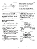
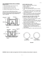
Страница 4: ...ecting tube for Models E 11 and E 23 4 Untighten four cylinder head fixed bolts 5 Remove cylinder head carefully and turn it over 6 Unbolt inlet valve receiver 70112 31020 7 Remove valve spring 70112 31070 and valve plate 70112 31030 Valves should be inspected approximately every 1 000 hours of operation Inspect the valve seats on cylinder head for dents cracks or wear Replace all defective parts ...

Страница 5: ...ace valve spring 70123 31070 and valve plate 70123 31030 on valve receiver 70123 31020 2 Place valve seat 70123 31010 unloading fork guide 70123 31090 unloading spring 70123 11230 and unloading fork 70123 31080 respectively 3 Tighten the valve assembly by tightening the hex nut 4 Check the valves to see if they can move freely in their guides and do not pinch or bind between the seat and guard leg...

Страница 6: ...on Care should be taken not to damage the piston 6 Inspect the ring grooves for nicks and carbon deposits Clean the ring grooves and remove the obstructions which might prevent the rings from moving freely To install new rings on the piston as follows Be careful not to damage the piston and rings 1 Install the oil control ring 70123 61050 first Rotate ring in groove to make sure it is free 2 Insta...

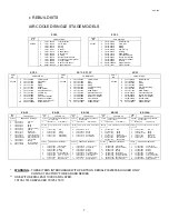
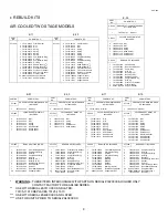
Страница 7: ...123 66140 Filter Kit 4 70123 31030 Disc 3 70123 66140 Filter Element 3 70123 66140 Filter Element 3 70123 66140 Filter Element 3 70123 66140 Filter Element 2 70123 31070 Spring 2 70123 41070 Spring CF1245 VALVE GASKET MAINT KIT INCLUDES CF1243 VALVE GASKET MAINT KIT INCLUDES CF1241 VALVE GASKET MAINT KIT INCLUDES CF1320 VALVE GASKET MAINT KIT INCLUDES 4 70123 61030 Compression Ring 4 70123 61050 O...

Страница 8: ...0153 31032 Disc 6 70123 31030 Disc 4 70124 31030 Disc 4 70125 31030 Disc 2 70153 32032 Disc 3 70123 31070 Spring 2 70123 31030 Disc 2 70175 42030 Disc 4 70153 31072 Spring 3 70123 41070 Spring 2 70124 31070 Spring 2 70125 31070 Spring 2 70153 32072 Spring 6 70123 11110 Seat Gasket 1 70123 31070 Spring 1 70124 31070 Spring 1 70153 31120 Head Gasket 3 70123 11612 Head Gasket 2 70124 41070 Spring 6 7...

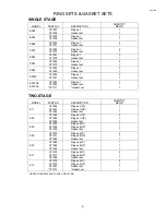
Страница 9: ...50 ES150A CF1265 CF1282 CF1311 Ring set Gasket set Gasket set 3 1 1 TWO STAGE MODEL PART NO DESCRIPTION QUANTITY REQ D E11 CF1266 CF1267 CF1283 Ring set LP Ring set HP Gasket set 1 1 1 E23 CF1268 CF1269 CF1284 Ring set LP Ring set HP Gasket set 2 1 1 E35 CF1303 CF1304 CF1305 Ring set LP Ring set HP Gasket set 1 1 1 E50 CF1270 CF1271 CF1285 Ring set LP Ring set HP Gasket set 2 1 1 E57 CF1288 CF1289...

Страница 10: ...111 61282 21 Oil Splash Dipper Bolt 1 91507 2304010 22 Oil Splash Dipper Bolt Washer Not Shown 1 92522 130400 Description QTY PART NO CRANKCASE AND CRANK ASSEMBLY 23 Crankshaft 1 70111 56010 24 Front Bearing Cover 1 70111 57030 25 Front Bearing Cover Gasket 1 70111 57950 26 Front Cover Bolts Not Shown 4 91501 1306016 27 Front Bearing 6203 1 93501 6203 28 Rear Bearing Cover 1 70111 57060 29 Rear Be...

Страница 11: ...rust Washer 1 70112 76210 11 Cylinder 2 70121 51010 43 Compressor Pulley Thrust Bolt 1 91501 1306025 12 Cylinder To Case Gasket 2 70121 51610 44 Oil Level Gauge Gauge Cover 1 70111 57700 13 Cylinder To Case Bolt Not Shown 8 91501 1306016 44A Oil Level Gauge Assy 1 70704 57700 14 Cylinder To Case Bolt Washer Not Shown 16 92521 190600 45 Oil Level Gauge Cover Seal 1 70111 57730 15 Compression Ring 4...

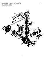
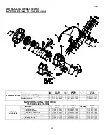
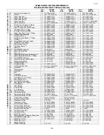
Страница 12: ...CAP 600 12 AIR COOLED SINGLE STAGE MODELS ES 05 ES 10 ES 20 ...

Страница 13: ...0 4024 1 70132 57010 4024 40 Crankshaft 1 70112 56010 1 70122 56010 1 70132 56010 41 Front Bearing Cover 1 70112 57030 1 70122 57030 1 70122 57030 42 Front Bearing Cover Gasket 1 70112 57950 1 70122 57950 1 70122 57950 43 Rear Bearing Cover 1 70112 57060 1 70122 57060 1 70122 57060 44 Rear Bearing Cover Gasket 1 70112 57960 1 70122 57960 1 70122 57960 45A Bearing Front 1 93501 6205 1 93501 6205 1 ...

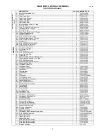
Страница 14: ...TING FOR MODELS ES 30 ES 50 ES 100 VALVE UNLOADERS Item No Description Qty Req MODEL ES30 Qty Req MODEL ES50 Qty Req MODEL ES100 1 Inlet Valve Seat 2 70123 31010 3 70123 31010 3 70124 31010 2 Inlet Valve Receiver 2 70123 31020 3 70123 31020 3 70124 31020 3 Inlet Outlet Valve Plate 4 70123 31030 6 70123 31030 6 70124 31030 4 Inlet Valve Spring 2 70123 31070 3 70123 31070 3 70124 31070 5 Inlet Valve...

Страница 15: ...250 6 70123 61250 6 70125 61250 34A Oil Splash Dipper H P 1 70122 61290 1 70134 62290 34 Oil Splash Dipper 2 70122 61282 2 70122 61282 2 70134 61281 35 Oil Splash Dipper Bolt 2 91507 2304012 3 91507 2304012 3 91507 2305016 CRANKCASE CRANK ASSEMBLY 42 Crankshaft 1 70123 56010 1 70133 56011 1 70134 56010 43 Counterweight 2 70134 56030 44 Lockwasher 2 70124 56830 45 Bolt 2 70124 56810 46 Crankcase 1 ...

Страница 16: ...ES 50A ES 100A VALVE UNLOADERS Item No Description Qty Req MODEL ES30A Qty Req MODEL ES50A Qty Req MODEL ES100A 1 Inlet Valve Seat 2 701208A1 31010 3 701208A1 31010 3 701210A1 31010 2 Inlet Valve Receiver 2 701208A1 31020 3 701208A1 31020 3 701210A1 31020 3 Inlet Outlet Valve Plate 2 701208A1 31030 6 701208A1 31030 6 501210A1 31030 4 Inlet Valve Spring 2 701208A1 31070 3 701208A1 31070 3 701210A1 ...

Страница 17: ...3 Connecting Rod Bolt 4 70123 61250 6 70123 61250 6 70125 61250 33A Oil Splash Dipper H P 1 70130FA1 61290 1 701310A1 61290 34 Oil Splash Dipper 2 70120FA1 61282 2 70120FA1 61282 2 701310A1 61281 35 Oil Splash Dipper Bolt 2 9151313 1104012 5602 3 9151313 1104012 5602 3 9151313 1105016 5602 CRANKCASE CRANK ASSEMBLY 42 Crankshaft 1 701208A1 56011 1 701308A1 56011 1 701310A1 56010 43 Counterweight 2 ...

Страница 18: ...25 41000 Breather Assembly 1 70124 57600 MAIN PARTS LISTING FOR MODEL ES 150 VALVE UNLOADERS DESCRIPTION Qty Req MODEL ES150 1 Inlet Valve Seat 3 70125 31010 2 Inlet Valve Receiver 3 70125 31021 3 Inlet Outlet Valve Plate 6 70125 31030 4 Inlet Valve Spring 3 70125 31070 5 Inlet Valve Unloading Fork Guide 3 70125 31090 6 Unloading Spring 3 70125 11230 7A Valve Gasket 6 70125 11110 ...

Страница 19: ...3 70125 61200 32 Connecting Rod Crank Pin Metal 6 70125 61090 33 Connecting Rod Bolt 6 70125 61250 34A Oil Splash Dipper H P 34 Oil Splash Dipper 3 70135 61281 35 Oil Splash Dipper Bolt 3 92501 130800 42 Crankshaft 1 70135 56011 43 Counterweight 2 70135 56031 44 Lockwasher 2 70135 56830 45 Bolt 2 70135 56811 46 Crankcase 1 70135 57010 4024 47 Front Bearing Cover 1 70135 57030 48 Front Bearing Cove...

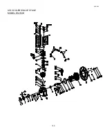
Страница 20: ...CAP 600 AIR COOLED SINGLE STAGE MODEL ES 150A 18 ...

Страница 21: ...CONN ROD ASS Y 3 37 70125 61250 CONN ROD ASS Y BOLT 6 38 50135 61081 CONN ROD CRANK PIN METL 3 39 70125 61070 PISTON PIN SNAP RING 6 40 70125 61120 PISTON PIN 3 41 70135 61010 1 PISTON 3 42 70135 61050 OIL CONTROL RING 6 43 70135 61030 COMPRESSION RING 6 44 70135 51011 CYLINDER 3 45 92501 131200 NUT 12 46 70135 11610 CYL HEAD PACKING 3 47 91501 1312035 BOLT 18 48 70135 11011 CYLINDER HEAD 3 49 701...

Страница 22: ...CAP 600 AIR COOLED SINGLE STAGE MODEL ES 150B 18A ...

Страница 23: ...ONN ROD ASS Y 3 37 70125 61250 CONN ROD ASS Y BOLT 6 38 501312A1 61081 CONN ROD CRANK PIN METL 3 39 701212A1 61070 PISTON PIN SNAP RING 6 40 701212A1 61120 PISTON PIN 3 41 701312A1 61010 PISTON 3 42 701212A1 61050 OIL CONTROL RING 6 43 701212A1 61030 COMPRESSION RING 6 44 701312A3 51010 CYLINDER 3 45 92501 131200 NUT 12 46 701312A3 11020 CYL HEAD GASKET 3 47 9250113 121200 538 BOLT 12 48 701312A3 ...

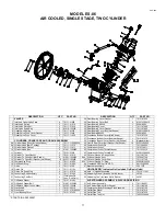
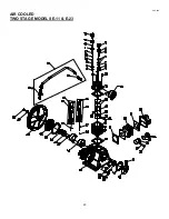
Страница 24: ...CAP 600 20 AIR COOLED TWO STAGE MODELS E 11 E 23 ...

Страница 25: ...ylinder Head 2nd 1 70162 12010 1 70172 12010 31 Cylinder Head Gasket 2nd 1 70162 12610 1 70111 11612 32 Cylinder 2nd 1 70162 52010 1 70172 52010 34 Compression Ring 2nd 2 70162 62030 2 70111 61030 35 Oil Control Ring 2nd 2 70162 62050 2 70111 61050 36 Piston 2nd 1 70162 62010 1 70172 62010 1 37 Piston Pin 2nd 1 70162 62120 1 70172 62120 38 Connecting Rod Assembly 2nd 1 70182 62200 CRANK ASSEMBLY 3...

Страница 26: ...let Valve Receiver 2 70123 31020 1 70123 31020 2 70124 31020 1 70123 31020 3 Inlet Outlet Valve Plate 4 70123 31030 2 70123 31030 4 70124 31030 2 70123 31030 4 Inlet Valve Spring 2 70123 31070 1 70123 31070 2 70124 31070 1 70123 31070 5 Inlet Valve Unloading Fork Guide 2 70123 31090 1 70123 31090 2 70124 31090 1 70123 31090 6 Unloading Spring 2 70123 11230 1 70123 11230 2 70124 11230 1 70123 11230...

Страница 27: ...61250 34 Oil Splash Dipper 2 70122 61282 1 70132 61290 2 70134 61281 1 70134 61290 35 Oil Splash Dipper Bolt 2 91507 2304012 1 91507 2304012 2 91507 2304012 1 91507 2304012 36 Cylinder Head 2nd 1 70123 11010 1 70174 12010 37 Cylinder 2nd 1 70173 52010 1 70174 52011 37A Cyl 2nd S N 3020000 Later Use 1 70174 52011 38 Compression Ring 2nd 3 70112 61030 3 70123 61030 39 Oil Control Ring 2nd 1 70112 61...

Страница 28: ...ES UNLOADERS 1 Inlet Valve Seat 2 70125 31010 1 70124 31010 2 Inlet Valve Receiver 2 70125 31022 1 70124 31020 3 Inlet Outlet Valve Plate 4 70125 31030 2 70175 42030 4 Inlet Valve Spring 2 70125 31070 1 70124 31070 5 Inlet Valve Unloading Fork Guide 2 70125 31090 1 70124 31090 6 Unloading Spring 2 70125 11230 1 70124 11230 7 Inlet Valve Unloading Fork 2 70125 31080 1 70124 31080 8 Slotted Nut 2 92...

Страница 29: ... Cylinder Head 2nd 1 70175 12010 37 Cylinder 2nd 1 70175 52010 38 Compression Ring 2nd 3 70124 61030 39 Oil Control Ring 2nd 2 70124 61050 40 Piston 2nd 1 70175 62010 1 40A Piston 2nd S N A409XXXX Later Use 1 70175 62011 1 41 Piston Pin 2nd 1 70175 62120 41A Piston Pin 2nd S N A409XXXX Later Use 1 70175 62121 CRANKCASE AND CRANK ASSEMBLY 42 Crankshaft 1 70135 56011 43 Crankshaft Counterweight 1 70...

Страница 30: ...CAP 600 AIR COOLED TWO STAGE MODEL E 25 25A ...

Страница 31: ...70178 61090 23 CONNECTING ROD BOLT 6 70178 61250 24 LOCKWASHER M12 6 92522 131200 25 NUT M12 6 92501 131200 8 26 CONNECTING ROD 3 70131EB2 61210 27 CONNECTING ROD PISTON PIN NEEDLE BEARING 3 93501 3230 28 PISTON PIN SNAP RING 6 93610 130032 29 PISTON 2ND 1 70131EB2 62120 30 PISTON 2ND 1 70131EB2 62010 31 OIL CONTROL RING 2ND 2 70178 62050 32 COMPRESSION RING 2ND 3 70178 62030 33 CYLINDER BOLT 1ST ...

Страница 32: ...SKET 1ST 4 70181EB3 31110 73 INLET VALVE RECEIVER 1ST 2 70181EB3 31020 74 INLET VALVE SPRING 1ST 6 70181EB3 31070 75 INLET VALVE PLATE 1 1ST 2 70181EB3 31050 76 INLET VALVE PLATE 2 1ST 2 70181EB3 31030 77 INLET VALVE SEAT 1ST 2 70181EB3 31010 78 INLET VALVE STUD 2 70181EB3 31810 79 OUTLET VALVE SEAT 1ST 2 70181EB3 41010 80 OUTLET VALVE SPRING 1ST 6 70181EB3 41070 81 OUTLET VALVE RECEIVER 1ST 2 701...

Страница 33: ...115 GEAR PUMP HOUSING 1 70131EB2 27010 116 STEEL BALL 1 9980113 20036 117 BALL VALVE RECEIVER 1 703213A1 28090 118 PRESSURE GAUGE 0 10K 1 9320611 2032213 119 BALL VALVE SPRING 1 703213A1 28080 120 REGULATOR SEALING 1 703213A1 28110 121 REGULATOR ADJUST NUT 1 703213A1 28130 122 REGULATOR ADJUST BOLT 1 703213A1 28120 123 GEAR PUMP SHAFT 1 703213A1 27070 124 DRIVE GEAR RING 1 703213A1 27130 125 DRIVE...

Страница 34: ...CAP 600 26 AIR COOLED TWO STAGE MODEL E 35 ...

Страница 35: ...Inter Cooler Body 1 70152 71110 46A Gasket Copper 1 70152 12280 DESCRIPTION QTY PART NO 47 Inter Cooler Body Gasket 1 70152 71622 48 Inter Cooler Cover 1 70152 71160 49 Spring Washer 4 92522 130600 50 Bolt 4 91501 1306016 51 Compression Ring 1 st 2 70152 61030 52 Oil Control Ring 1 st 1 70152 61050 53 Piston 1 st 1 70152 61010 54 Piston Snap Ring 4 70152 61070 55 Connection Rod Assembly 1 st 1 701...

Страница 36: ...AIR COOLED TWO STAGE MODEL E 57 E57A CAP600 28 ...

Страница 37: ...22 130600 51 Bolt 6 91501 1306016 DESCRIPTION QTY PART NO 52 Compression Ring 1 st 2 70124 61030 53 Oil Control Ring 1 st 2 70124 61050 54 Piston 1 st 1 70153 61011 55 Piston Pin Snap Ring 4 70153 61071 56 Connection Rod Assembly 1 st 1 70153 61211 56A Connecting Rod Assembly 1 st 1 70153 62211 57 Piston Pin Bush 1 st 1 70153 61081 58 Connecting Rod Assembly 2 nd 1 70153 62211 59 Piston Pin Bush 2...

Страница 38: ...se new valve seat gasket B6 Place valve seat gasket in position on lower valve plate B7 Place upper valve seat with valve springs and plates tied in position on top of lower valve seat with new valve seat gasket in place between the two seats B8 Start center and then two end valve plates socket head bolts tighten finger tight being careful not to damage seat gasket use socket head wrench to torque...

Страница 39: ...CAP 600 31 VALVE PLATES DESIGNS FOR E 57 COMPRESSOR ...

Страница 40: ...ORQUE CM FT 135 9 7 180 13 0 135 9 7 180 13 0 180 13 0 180 13 0 180 13 0 280 20 25 180 13 280 20 25 280 20 25 280 20 25 300 21 7 300 21 7 320 23 1 320 23 1 ROD BOLTS SIZE BOLT M6 1 M8 1 25 M6 1 M8 1 25 M8 1 25 M8 1 25 M8 1 25 M10 1 5 M8 1 25 M8 1 5 M8 1 5 M8 1 25 M8 1 5 M8 1 5 M10 1 5 M10 1 5 TORQUE CM FT 200 14 5 120 8 7 200 14 5 200 14 5 200 14 5 200 14 5 280 20 25 200 14 5 280 20 25 280 20 25 2...

Страница 41: ...FLYWHEEL BOLTS FAN BOLTS MODEL NO TORQUE FT LBS TORQUE IN LBS TORQUE FT LBS TORQUE IN LBS ES03 8 96 ES05 ES06 ES10 E11 ES20 E23 E35 12 144 E57 23 276 ES30 30 360 ES50 E50 40 480 E71 ES100 45 540 24 288 E15 ES150 50 600 24 288 ...

Страница 42: ...00 1 2 PINTS ES06 3 4 500 10 OUNCES ES10 1 500 1 PINTS ES20 2 3 500 1 PINTS ES30 3 5 500 1 PINTS ES50 5 7 500 1 QUARTS ES100 7 10 500 2 QUARTS ES150 ES150A 15 500 5 QUARTS E11 1 500 1 PINTS E23 2 3 500 1 PINTS E35 3 5 500 2 PINTS E50 5 500 1 QUARTS E57 5 7 500 2 QUARTS E71 10 500 2 QUARTS E15 15 500 5 QUARTS ...

Страница 43: ...pair or replace safety valve 5 Tighten the nuts even with packing 6 Remove and lap the surface 7 Replace with new ones 8 Replace packing gasket 9 Eliminate air leaks Inaccuracy of pressure gauge Pressure gauge damaged Replace Excessive oil consumption 1 Worn piston ring 2 Worn piston 3 Worn cylinder 1 Replace 2 Replace 3 Replace Slipping of belts 1 Working pressure too high 2 Improper belt tension...

Страница 44: ...c equipment and tools prevents air line freeze ups and reduces product rejects The use of dryer s filters is recommended when this moisture related problems are reported to our factory or distributor service departments Troubleshooting guide Symptom Liquid water present in compressed air lines Problem Water vapor condensation from cooling and compression occurs naturally Solution Remove the water ...

Страница 45: ...x 50 60 5 25 0 56 5 5E2HT8 900 21 47 20 x 66 80 7 14 1 14 5 5E2VT8 900 21 47 20 x 48 80 7 14 1 14 7 1 2 7E2HT8 1100 26 24 20 x 66 80 6 16 1 05 7 1 2 7E2VT8 1100 26 24 24 x 48 80 6 16 1 05 7 1 2 7HT8 764 29 57 20 x 66 80 5 22 0 55 10 10HT8 977 37 81 20 x 66 80 4 11 0 43 10 10HT12 977 37 81 24 x 70 120 6 17 1 5 10 10VT12 977 37 81 30 x 47 120 6 17 1 5 15 15HT12 855 54 55 24 x 70 120 4 28 0 46 TWO ST...

Страница 46: ...97 20 x 50 60 6 16 1 15 5 5ES20VS6 1000 16 9 20 x 50 60 6 4 1 13 5 5HS6 945 20 13 20 x 50 60 4 8 0 50 5 5VS6 945 20 13 20 x 50 60 4 8 0 50 5 5HS6 945 20 13 20 x 66 80 5 31 1 6 5 5VS8 945 20 13 24 x 48 80 5 31 1 6 7 1 2 7HS8 945 30 14 20 x 66 80 3 35 0 43 7 1 2 7VS8 945 30 14 24 x 48 80 3 35 0 43 10 10HS8 866 50 4 20 x 66 80 2 7 0 25 10 10HS12 866 50 4 24 x 70 120 3 10 0 38 10 10VS12 866 50 4 30 x ...

Страница 47: ...CAP 600 NOTES 39 ...

Страница 48: ...CURTIS TOLEDO INC 1905 KIENLEN AVE ST LOUIS MO 63133 TEL 314 383 1300 FAX 314 381 1439 E MAIL info curtistoledo com www curtistoledo com ...

Отзывы: