


CAP-600
5
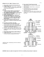
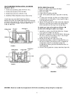
MODELS E-50, E-71 AND E-15 (Figures 4 and 5)
A.
Disassembly of Inlet Valve Assembly (Figure 4)
.
1. Untighten the hex nut.
2. Remove unloading fork (70123-31080), unloading fork
guide (70123-31090), unloading spring (70123-11230)
and valve seat (70123-31010).
CAUTION:
1. If a vise is used to hold the valve assembly, be
careful not to clamp the assembly too tight.
2. Valve assembly should be inspected approximately
every 1,000 hours of operation.
3. Inspect the valve seat for dents, cracks or wear.
4. Replace all defective parts.
5. Valve seats that might be worn after years of
operation can be re-lapped or re-ground, in this
case the recess in which the valve guard legs fit
must also be cut down accordingly to ensure a
same valve lift.
FIGURE 4
(EXAMPLE SHOWN E-50)
FIGURE 5
(EXAMPLE SHOWN E-50)
6. Remove carbon deposits and wash all valve
components in a suitable non-flammable cleaning
fluid.
B. Reassembly of Inlet Valve Assembly
1. Place valve spring (70123-31070) and valve plate
(70123-31030) on valve receiver (70123-31020).
2. Place valve seat (70123-31010), unloading fork guide
70123-31090), unloading spring (70123- 11230) and
unloading fork (70123-31080) respectively.
3. Tighten the valve assembly by tightening the hex nut.
4. Check the valves to see if they can move freely in their
guides and do not pinch or bind between the seat and
guard legs.
C.
Disassembly of Outlet Valve Assembly (Figure 5)
1. Untighten the hex nuts.
2. Remove valve receiver (70123-41020), valve spring
(70123-41070) and valve plate (70123-31030).
CAUTION: Refer to disassembly of inlet valve assembly
(paragraph B).
D. Reassembly of Outlet Valve Assembly
1. Place valve spring (70123-41070) in valve receiver
70123-41020).
2. Place valve plate (70123-31030) in valve receiver.
(70123-41020).
3. Insert the sub-assembled part (assembled in
step I and 2) into valve seat (70123-41010).
4. Tighten the hex nuts.
5. Check the valves to see if they can move freely in their
guides and do not pinch or bind between the seat and
guard legs.
WARNING: Read and understand supplement LV-474 before installing and operating the compressor.
Содержание CA series
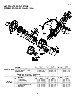
Страница 12: ...CAP 600 12 AIR COOLED SINGLE STAGE MODELS ES 05 ES 10 ES 20 ...
Страница 20: ...CAP 600 AIR COOLED SINGLE STAGE MODEL ES 150A 18 ...
Страница 22: ...CAP 600 AIR COOLED SINGLE STAGE MODEL ES 150B 18A ...
Страница 24: ...CAP 600 20 AIR COOLED TWO STAGE MODELS E 11 E 23 ...
Страница 30: ...CAP 600 AIR COOLED TWO STAGE MODEL E 25 25A ...
Страница 34: ...CAP 600 26 AIR COOLED TWO STAGE MODEL E 35 ...
Страница 36: ...AIR COOLED TWO STAGE MODEL E 57 E57A CAP600 28 ...
Страница 39: ...CAP 600 31 VALVE PLATES DESIGNS FOR E 57 COMPRESSOR ...
Страница 47: ...CAP 600 NOTES 39 ...