CA / CT SERIES
CAP600
Page 5 of 30
REV D July 2013
System Diagram
Simplex Units
1
2
3
4
5
6
Air Intake
Air Compressor
Intercooler
Magnetic Starter
Pressure Switch
Vibration Pads with
hardware mounts
1
Exact orientation of system components
may vary. Please see your model's general
arrangement diagram for a precise
configuration of system components.
6
2
3
4
5
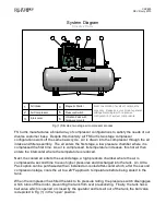
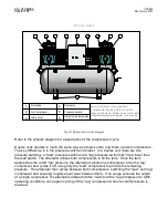
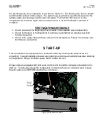
Fig. (1) Simplex, two stage air compressor process.
FS Curtis manufactures a broad array of compressor configurations to satisfy the needs of our
diverse customer base. Despite this diversity, all FS Curtis two stage compressor
configurations work off the same basic cycle. Air is drawn into the compressor through the air
intake and filter assembly. The air enters the first stage, a low pressure chamber where it is
compressed the first time. As air is compressed, its temperature increases, this hot air then
enters the intercooler where the temperature is reduced.
Next, the cooled air enters the second stage, a high pressure chamber where the air is
compressed a second time to even higher pressures and discharged into the tank. An Ultra
Pack option can be purchased with an installed air-cooled after-cooler which, after the second
compression stage, cools the air to a 20°F approach temperature before being stored in the
tank.
When the compressor has filled the tank to its pressure rating, the pressure switch disengages
which turns off the motor, preventing the tank from over pressurizing. Finally, the tank has a
ball valve which is opened or closed by the operator and lets air out of the tank, the ball valve
is depicted in Fig (1) in the “open” position.


