


Instructor User Guide
Advanced
Advanced
13 Oct 2017
Page 241
16.3.1
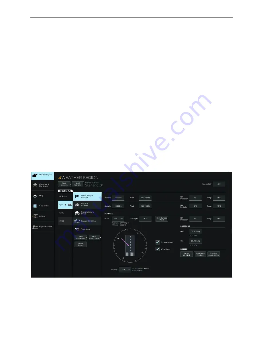
WEATHER REGION
WEATHER REGION provides all necessary controls to alter environmental
conditions for up to five different airports and en route weather conditions.
For a specific region, the instructor can alter the current region parameters listed
below:
•
Winds, temperature and pressure
•
Clouds and visibility conditions
•
Precipitation
•
Runway conditions
•
Turbulence
WEATHER REGION offers the possibility of:
•
Saving the current region weather parameters into a Scenario
•
Recalling previously saved region weather scenarios
•
Adding a Region
•
Deleting Scenarios
Figure 148 Advanced
– Weather Region (Typical)
Содержание A320 SIDESTICK PRO OEM
Страница 1: ...13 Oct 2017 A320Neo 1UI ISS IUG_Rev0 A320 Instructor Operating Station Instructor User Guide ...
Страница 2: ......
Страница 4: ......
Страница 6: ......
Страница 26: ......
Страница 32: ......
Страница 34: ......
Страница 36: ......
Страница 38: ......
Страница 50: ......
Страница 54: ......
Страница 60: ...A320 Neo Instructor Operating Station Instructor User Guide DOCS Tab 13 Oct 2017 Page 26 Figure 16 DOCS Tab ...
Страница 126: ......
Страница 128: ......
Страница 196: ......
Страница 205: ...Instructor User Guide Control Board Footer Control Board Footer 13 Oct 2017 Page 171 Figure 87 Session Reset ...
Страница 238: ......


