


15-5
18.
If the display fails to perform in this manner, check connection between ribbon cable and display
driver, ribbon cable and display assembly and non-terminated ribbon cable and membrane
switch.
19.
Turn off power. Reconnect CN2 connector. Install sides and return unit to operation.
15.3 Removing a Slot
1.
Perform steps in Section 15-1, Steps 1-7.
Disconnect heater and control wiring to the slot
being removed (
Fig. 16
).
2.
Using a 7/16” nut driver, loosen the four ¼ - 20
hex-head mounting screws from each corner of the
slot to be removed. Loosen one full turn, but do not
remove.
3.
Remove wire wraps from wiring harness holding
heater and control wires for affected slot.
4.
Lifting slightly, carefully slide the malfunctioning
slot out of the cabinet. Do not allow the slot to
contact and damage the controls of the unit below.
5.
Perform Section 15-1, Steps 9 – 11.
Fig: 15:
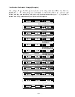
In the test mode, asterisk-like symbols will illuminate in the displays, appearing to march from
display to display from left to right. In units with rear displays, this light motion is repeated on the rear
displays.
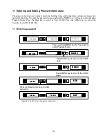
Note:
The rear display is differentiated from the front by the absence of UP/DOWN arrows and a MENU
switch.
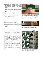
Fig. 16.
Disconnect heater and control
wiring from component shelf.
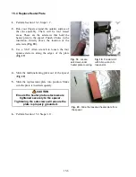
Fig. 17.
Slide malfunctioning slot from
cabinet.
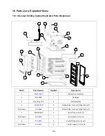
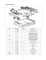
Содержание Universal Holding Cabinet
Страница 46: ...17 1 17 Wiring Diagram UHC...