


14-2
14.4 Master Board/Display Driver
1.
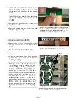
To isolate between a defective master board or display driver, disconnect the front and rear
ribbon cables (FC1 and FC2) and the CN2 connector on the suspect display driver. Disconnect
the front and rear ribbon cables and the CN2 connector on the nearest display driver, which
operates correctly.
2.
Connect the connectors from the suspect display driver to a known good display driver and test
the operation. If the malfunction continues, replace the master board. If the malfunction is
corrected, replace the defective display driver.
NOTE:
After testing, reconnect all connections to their original positions.
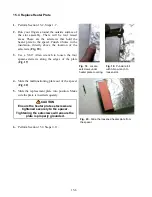
14.5 Shorted Triac
1.
Turn the suspect slot off and measure voltage from the white terminal block to the top (black
lead) heater plate. Also, measure voltage to the bottom heater plate. With slot off, there should be
no line voltage. If the triac is shorted, you will measure AC line voltage. If the triac is half
waving, you will get DC voltage of approximately one-half the line AC voltage. Also, with the
slot off, measure the slot temperature. If the slot is heating, it is miswired or the master control
board is defective (shorted triac).
14.6 Display Driver/Display Isolation Test
1.
On stand-alone units, disconnect power to the cabinet and remove side and top panels. If unit is
stacked, see service procedures for instructions on accessing the top panel.
2.
Disconnect CN2 connector on the suspect display driver. Apply power. The selected display will
indicate
Disp Test Mode.
(Note: All slots below the selected slot will not operate.) Press
each functional button on the selected display, starting with the timer key at the left. Each button
must be pressed in sequential order, starting at the left on the front display and continuing to the
rear display on all slots. After all buttons have been pressed, each LED display segment should
illuminate sequentially.
3.
If the unit does not perform as described in step 2, isolate between a bad display or display driver
by connecting the ribbon connector form the suspect display to one or the know good display
drives and repeat the test.
NOTE:
There is no output from the master control board during this test. If the unit does not
operate as described in step 2, the problem cannot be the master control board.
Содержание Universal Holding Cabinet
Страница 46: ...17 1 17 Wiring Diagram UHC...