6 horstCONTROL I/O
38
The following functions can be configured for the safe inputs (see
Software Configuration Options for
Function
Stop
category
Description
None
-
Emergency stop
1
Signals an internal emergency stop Emergency stop output is
set.
External emergency stop
1
External system signal emergency stop. Emergency stop output
is not set.
Safety Stop
1
Protection devices that are not active in teaching mode with an
enabling switch can be connected here. This means the cell can
be entered during teaching.
Only active in automatic mode.
Safety stop
Self-triggering
2
Like the safety stop, but automatic reset and restart of the robot
after recovery of the safe state.
Enabling switch
2
Safe stop, if enabling switch is pushed through or is not pressed.
Reduced speed
0
Checks the saved, reduced speeds. If the robot moves faster
than the reduced speed, a Stop Category 0 is triggered.
Two digital inputs
-
Safe input is configured as two general digital inputs.
Table 6-4: Configurable functions for safe inputs
Here too the following applies: The system is always in a safe state with "low" signals (0 V,
logical 0), e.g. robot has a low signal at the external emergency stop input.
6.4.2.4
Safe Outputs
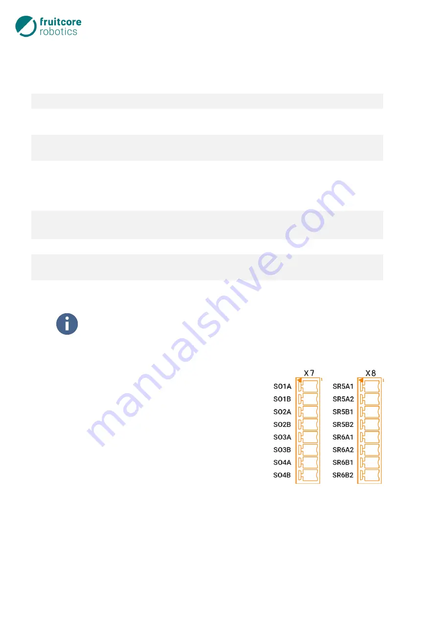
There are 6 configurable, safe outputs. These are also designed re-
dundantly with Performance Level “d”, Category 3, in accordance
with EN ISO 13849-1, although outputs SR5 and SR6 (Safety Relay
Out) are each implemented as potential-free contacts by means of
positively controlled relays. With these outputs, it is possible to tell
other machines what state the robot is in.
The relay contacts can be loaded with 5 A and 24 V and are brought
out at terminal block X8.
The safe outputs SO1 to SO4 (Safety Out) at terminal block X7 cor-
respond to the electrical specification of the digital outputs but are
not coupled with the total current limit (see
page 42). These are always configured as Push-Pull outputs.
Each of these outputs can be used without OSSD function (chronologically offset 400
µ
s Low Impulse) or
al a general digital output.
For each safe output, two normal digital inputs can be configured as additional read-back inputs. This
enables safe switching of an external, positively controlled contactor or relay with read-back of the auxil-
iary contact states. An inverted or non-inverted signal can be used here. If an invalid read-back signal is
detected, a Category 1 stop is triggered.
Fig. 6-9: Connection of safe outputs
Содержание HORST600
Страница 3: ...3 ...


