background image

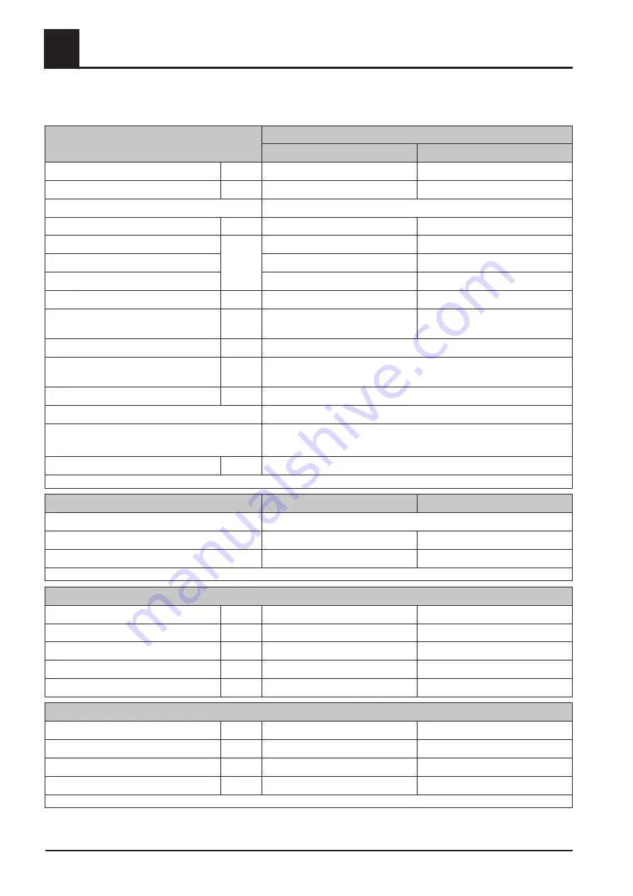
3.3 Technical specifications

Description

TM

400

500

Nominal heat output

kW

399

499

Heat output range

kW

119-399

149-499

Electrical connection

400 V / 50 Hz / 35 A or as per circuit diagram

Power consumption (pellets, wood chip)

kW

1.38 / 1.75

1.57 / 2.08

Total weight incl. fittings

kg

8,400

8,400

Weight - combustion chamber

2,200

2,200

Weight - heat exchanger

2,150

2,150

Heat exchanger water capacity

l

750

750

Water pressure drop 

(ΔT = 10 / 20 K)

mbar

14.3 / 5.6

19 / 8.5

Minimum boiler return temperature

°C

65

Maximum permitted operating tempera‐

ture

°C

90

Permitted operating pressure

bar

6

Boiler class as per EN 303-5:2012

5

Permitted fuel as per EN 14961 

1)

Part 2: Wood pellets class A1 / D06

Part 4: Wood chips class A2 / P16A-P45A

Airborne sound level

dB(A)

< 70

1.Detailed information on the fuel is included in the operating instructions in the section on “Permitted fuels”


400

500

Testing institute

TÜV Austria

1)

Test report no.

11-UW/Wels-EX-177/5

11-UW/Wels-EX-177/1

Date of issue

20/03/2012

18/09/2011

1.TÜV Austria Services GmbH, Geschäftsbereich Umweltschutz, Am Thalbach 15, A-4600 Thalheim/Wels

Test data for wood chips - emissions in [mg/MJ] (nominal load/partial load)

Carbon monoxide (CO)

mg/MJ

9 / 4

<2 / 4

Nitrogen oxide (NOx)

mg/MJ

44 / 51

46 / 51

Organic hydrocarbons (OGC)

mg/MJ

<1 / <2

<1 / <2

Dust

mg/MJ

15 / 11

18 / 11

Boiler efficiency

%

93.9 / 90.3

93.6 / 90.3

Test data for wood chips - emissions in [mg/m³]

1)

 (nominal load/partial load)

Carbon monoxide (CO)

mg/m³

14 / 5

<2 / 5

Nitrogen oxide (NOx)

mg/m³

65 / 76

67 / 76

Organic hydrocarbons (OGC)

mg/m³

<1 / <3

<1 / <3

Dust

mg/m³

22 / 16

26 / 16

1.Emissions values based on dry flue gas at standard temperature and pressure (0°C, 1,013 mbar) with a volume content of oxygen of 13%

3

Technology

Technical specifications

14

Fröling GesmbH | 4710 Grieskirchen, Industriestraße 12 | www.froeling.at

Содержание Turbomat TM 400

Страница 1: ...inal German installation instructions for technicians Read and follow the instructions and safety information Technical changes typographical errors and omissions reserved M0690213_en Edition 31 03 2014 Fröling GesmbH 4710 Grieskirchen Industriestraße 12 www froeling at ...

Страница 2: ...d connections 13 3 3 Technical specifications 14 4 Assembly 16 4 1 Transport 16 4 2 Positioning 16 4 3 Temporary storage 16 4 4 Setting up in the boiler room 16 4 4 1 Moving the boiler in the boiler room 16 4 4 2 Minimum distances in the boiler room 17 4 5 Installing the boiler 18 4 5 1 General information 18 4 5 2 Bolting together the combustion chamber and heat exchanger 18 4 5 3 Assembling the ...

Страница 3: ...8 4 5 24 Installing the boiler controller when operating the burner optional 59 4 6 Power connection and wiring 60 4 7 Thermal discharge safety device connection 61 4 8 Connecting the slide on duct cooling 62 5 Commissioning 63 5 1 Before commissioning configuring the boiler 63 5 2 Initial startup 64 5 2 1 Permitted fuels 64 Wood chips 64 Wood pellets 64 Wood shavings 64 Miscanthus 65 Changing the...

Страница 4: ...or dif ferences from the pictures and content If you discover any errors please let us know doku froeling com Subject to technical change The EC Declaration of Conformity is only valid in conjunction with a delivery certificate which has been filled in correctly and signed as part of the commissioning process The original document remains at the installation site Commissioning installers or heatin...

Страница 5: ...rved it will lead to serious injury or death You must follow the instructions WARNING The dangerous situation may occur and if measures are not observed it will lead to serious injury or death Work with extreme care CAUTION The dangerous situation may occur and if measures are not observed it will lead to minor injuries or damage to property Safety 2 Hazard levels of warnings Installation Instruct...

Страница 6: ...re that staff have the protective equipment specified by accident pre vention regulations For transportation setup and assembly suitable workwear protective gloves sturdy shoes 2 4 Design Information 2 4 1 Notes on standards The system must be installed and commissioned in accordance with the local fire and building regulations The following standards and regulations should always be ob served Gen...

Страница 7: ...I 97 1 Water quality for heating steam cooling and air conditioning systems Switzerland D P R no 412 Regulations for the planning installation running operation and maintenance of heating systems in buildings to reduce energy consumption with reference to Article 4 Comma 4 of the Legis lative Decree of 9 January 1991 No 10 Italy Standards for permitted fuels EN 14961 2 Solid biofuel fuel specifica...

Страница 8: ...ing must not be put on the boiler to dry Damage due to impurities in combustion air Do not use any solvents or cleaning agents containing chlorine in the room where the boiler is installed Keep the air suction opening of the boiler free from dust Ventilation of the boiler room Ventilation air for the boiler room should be taken from and expelled directly outside and the openings and air ducts shou...

Страница 9: ... air is released by means of a solenoid valve The systems are built solely with closed diaphragm expansion tanks to prevent the damaging introduction of oxygen in to the heating water Pump controlled pressure maintenance A pump controlled pressure maintenance unit essentially consists of a pressure main tenance pump relief valve and an unpressurised receiving tank The valve releases hot water into...

Страница 10: ...The minimum return temperature is 65 C We recommend fitting some sort of control device e g thermometer 2 4 7 Use with storage tank NOTICE In principle it is not necessary to use a storage tank for the system to run smooth ly However we recommend that you use the system with a storage tank as this ensures a continuous supply of fuel in the ideal output range of the boiler For the correct dimension...

Страница 11: ... EN 13384 1 Local regulations and other statutory regulations also apply NOTICE The chimney must be authorised by a smoke trap sweeper or chimney sweep Draught limiter The installation of a draught limiter is recommended NOTICE Install the draught limiter directly under the mouth of the flue line as the pressure is constantly low at this point Boiler data for planning the flue gas system Descripti...

Страница 12: ... Height flue gas pipe connection excl flue gas return mm 985 985 H5 Height flue gas pipe connection incl flue gas return mm 2 075 2 075 B Total width incl fittings mm 2 990 2 990 B1 Width boiler incl insulation mm 2 495 2 495 L Total length incl fittings mm 3 595 3 595 L1 Length stoker unit mm 1 050 1 050 3 Technology Dimensions 12 Fröling GesmbH 4710 Grieskirchen Industriestraße 12 www froeling a...

Страница 13: ...nection inches DN100 PN 16 C Thermal discharge safety device connection inches ET ET D Flue gas pipe connection without FGR flue gas recir culation mm 350 350 E Flue gas pipe connection with FGR flue gas recircu lation mm 350 350 Technology 3 Components and connections Installation Instructions Turbomat TM 400 500 M0690213_en 13 ...

Страница 14: ... included in the operating instructions in the section on Permitted fuels 400 500 Testing institute TÜV Austria1 Test report no 11 UW Wels EX 177 5 11 UW Wels EX 177 1 Date of issue 20 03 2012 18 09 2011 1 TÜV Austria Services GmbH Geschäftsbereich Umweltschutz Am Thalbach 15 A 4600 Thalheim Wels Test data for wood chips emissions in mg MJ nominal load partial load Carbon monoxide CO mg MJ 9 4 2 4...

Страница 15: ... 92 0 Test data for pellets emissions in mg m 1 nominal load partial load Carbon monoxide CO mg m 3 4 2 4 Nitrogen oxide NOx mg m 93 105 97 105 Organic hydrocarbons OGC mg m 1 2 1 2 Dust mg m 17 15 19 15 1 Emissions values based on dry flue gas at standard temperature and pressure 0 C 1 013 mbar with a volume content of oxygen of 13 Technology 3 Technical specifications Installation Instructions T...

Страница 16: ...ng device to the eyelet s on the boiler 4 3 Temporary storage If the system is to be assembled at a later stage Store components at a protected location which is dry and free from dust Damp conditions and frost can damage components particularly electric ones 4 4 Setting up in the boiler room 4 4 1 Moving the boiler in the boiler room Position a fork lift or similar lifting device with a suitable ...

Страница 17: ...s and regulations when setting up the system Observe additional standards for noise protection ÖNORM H 5190 Noise protection measures A B D C Item Description Unit TM 400 500 A Space required for inspection area of infeed mm 500 B Space required for inspection area of heat exchanger lateral 500 C Space required for inspection area front 1 000 D Space required for inspection area of combustion cham...

Страница 18: ...and is where the stoker unit EOS drive and complete flue gas system can be found Heat exchanger on the left or right A general distinction is made between whether the heat exchanger is located to the left or right of the combustion chamber as seen from the front operating side It is important to determine whether the heat exchanger will be installed to the left or right if there is no existing lay...

Страница 19: ...caps on the end of the grate shafts If necessary tighten to the stop Fix the heat exchanger to the flange with 6 M12 nuts and washers socket span ner size SW 19 mm Tighten the nuts so that the flange ring is seated inside the cord seal channel Assembly 4 Installing the boiler Installation Instructions Turbomat TM 400 500 M0690213_en 19 ...

Страница 20: ...ts and M10 nuts Secure the flange plate with 4 M10x20 bolts and M10 nuts Fix the rotary valve or the burn back flap depending on the version in place using four M12 screws and nuts Fit the burn back flap so that the pivot point of the flap is on the side opposite the boiler Push in the stoker screw Fit the flange plate onto the stoker screw and align it parallel to the stoker duct flange Check tha...

Страница 21: ...tted to the back of the boiler The EOS rods may therefore need repositioning depending on the side where the heat exchanger is fitted Open the heat exchanger cover Loosen the clamping jaw on the operating lever and remove it from the heat ex changer shaft Unscrew the bearing bush on the shaft Unscrew the blind plug mounted on the opposite side of the heat exchanger shaft Remove the securing pins f...

Страница 22: ...cover plate to the duct Fix the air damper rods in place with a pressure spring spacer washer and air flap Fix the glass fibre braid onto the air controller cover plate and attach the cover plate to the duct Assemble the torque support for the actuator on the cover plate 4 Assembly Installing the boiler 22 Fröling GesmbH 4710 Grieskirchen Industriestraße 12 www froeling at ...

Страница 23: ...amber longitudi nal element F Back heat exchanger cross piece C Back combustion chamber cross piece G Angled elements D Front combustion chamber cross piece H Right heat exchanger longitudinal ele ment Position the left combustion chamber longitudinal element A Assembly 4 Installing the boiler Installation Instructions Turbomat TM 400 500 M0690213_en 23 ...

Страница 24: ...s piece The lugs on the cross pieces and longitudinal elements must overlap correctly 1 Attach the cross pieces to the combustion chamber at the specified points Fix the cross pieces to the longitudinal elements with thread forming screws Position the heat exchanger front E and back F cross pieces on the heat ex changer 4 Assembly Installing the boiler 24 Fröling GesmbH 4710 Grieskirchen Industrie...

Страница 25: ...the heat exchanger at the angled elements Fix the front and back cross pieces to the heat exchanger longitudinal element on the right and to the combustion chamber longitudinal element on the left with thread forming screws Align the floor base frame on all sides using M8x40 hexagon bolts Assembly 4 Installing the boiler Installation Instructions Turbomat TM 400 500 M0690213_en 25 ...

Страница 26: ...lation mat from the back left over the combustion chamber Insert the other end of the heat insulation mat between the combustion cham ber and heat exchanger Front Back Lay the heat insulation mat over the combustion chamber from the front from the front of the boiler right underneath and up to above the secondary air box on the back of the boiler 4 Assembly Installing the boiler 26 Fröling GesmbH ...

Страница 27: ...from the side View of the combustion chamber from the right Fix the heat insulation mats in place using tension springs View of the combustion chamber from the back Assembly 4 Installing the boiler Installation Instructions Turbomat TM 400 500 M0690213_en 27 ...

Страница 28: ... Left combustion chamber longitudi nal element F Heat exchanger support element C Combustion chamber cross pieces G Heat exchanger cross pieces D Right combustion chamber longitu dinal element H Heat exchanger longitudinal element 4 Assembly Installing the boiler 28 Fröling GesmbH 4710 Grieskirchen Industriestraße 12 www froeling at ...

Страница 29: ... tension springs Position the left combustion chamber longitudinal element B on the support ele ments Position the combustion chamber cross pieces at the front and back between the support elements Position the right combustion chamber longitudinal element D on the support ele ments Assembly 4 Installing the boiler Installation Instructions Turbomat TM 400 500 M0690213_en 29 ...

Страница 30: ...gs are placed correctly Line up the frame and screw the frame elements in place Insert the heat exchanger support element F into the floor base frame Position the heat exchanger cross pieces G and longitudinal elements H 4 Assembly Installing the boiler 30 Fröling GesmbH 4710 Grieskirchen Industriestraße 12 www froeling at ...

Страница 31: ...ove the protective film from all of the insulating side panels Cut out all of the perforated areas from the insulating side panels depending on the boiler in question Cut away and remove any thermal insulation below the panels using a knife Assembly 4 Installing the boiler Installation Instructions Turbomat TM 400 500 M0690213_en 31 ...

Страница 32: ... panel 1 into place at the top and onto the lugs in the frame 3 Slide insulating side panel A into the upper and lower frames Slide insulating side panels B and C into place Slide insulating side panels D and E into place 4 Assembly Installing the boiler 32 Fröling GesmbH 4710 Grieskirchen Industriestraße 12 www froeling at ...

Страница 33: ...e Slide insulating side panels J and K into place Attach all insulating side panels to the frame with screws Position the heat exchanger ash removal insulation L and attach at the top using three screws Assembly 4 Installing the boiler Installation Instructions Turbomat TM 400 500 M0690213_en 33 ...

Страница 34: ... side panel O into place Mount the cover plate two parts onto the case cooling optional If there is no case cooling the cover plate is a single piece Mount the cover plate to the left of the case cooling 4 Assembly Installing the boiler 34 Fröling GesmbH 4710 Grieskirchen Industriestraße 12 www froeling at ...

Страница 35: ... both flanges 1 for the heat exchanger ash removal Grease the shaft stub on both ash screws Place the motor on the right hand shaft and fix in place with screws Front of boiler Back of boiler Assembly 4 Installing the boiler Installation Instructions Turbomat TM 400 500 M0690213_en 35 ...

Страница 36: ...unt a simple chain wheel onto the geared motor Mount the chain wheel and chain tensioner on the pedestal Wind the chain around the motor and pedestal and hold in place using the spacer sleeve 4 Assembly Installing the boiler 36 Fröling GesmbH 4710 Grieskirchen Industriestraße 12 www froeling at ...

Страница 37: ...nto the ash removal flanges as shown in the diagram Fit the foam rubber seal on the ash removal flanges over the shaft Fit the plastic handles on the locking levers If necessary use a rubber mallet to knock it into place Assembling the ash box locking lever Assembly 4 Installing the boiler Installation Instructions Turbomat TM 400 500 M0690213_en 37 ...

Страница 38: ...ing mechanism face outwards Install the insulation Mount the lower bracket to the insulation Position both ash cans on the flanges Push the lever on the side of the boiler downwards to lock the ash container in place Front of boiler 4 Assembly Installing the boiler 38 Fröling GesmbH 4710 Grieskirchen Industriestraße 12 www froeling at ...

Страница 39: ...er 4 5 11 Installing the induced draught fan Fit seal cord around the induced draught fan flange on the back of the boiler Mount the induce draught fan bracket onto the flange Align correctly using the adjustable feet and fix in place using the spacer wash er and hexagon bolt Assembly 4 Installing the boiler Installation Instructions Turbomat TM 400 500 M0690213_en 39 ...

Страница 40: ...e onto the in duced draught fan Fit the broadband probe Unscrew the pre installed bushing from the broadband probe Screw the bushing into the induced draught fan flange and gently tighten Screw the broadband probe into the bushing and gently tighten using an Allen wrench 22 mm Screw in the brass bushing for the flue gas temperature sensor Push the flue gas temperature sensor in so that it protrude...

Страница 41: ...te to the insulation Lay the upper induced draught fan flange cover plate in place and fix with screws Run the cable from the broadband probe and flue gas temperature sensor out from the provided opening 1 4 5 12 Assembling the FGR optional Mount the FGR duct to the flue pipe elbow on the back of the boiler Mount the FGR bracket onto the flue pipe elbow Assembly 4 Installing the boiler Installatio...

Страница 42: ...he FGR blower fan using rubber buffers Wrap the complete FGR duct incl the flue pipe elbow in thermal insulation Fix the thermal insulation in place using tension springs Mount the vertical cover on the FGR duct 4 Assembly Installing the boiler 42 Fröling GesmbH 4710 Grieskirchen Industriestraße 12 www froeling at ...

Страница 43: ...e flue pipe elbow Mount all the inspection opening covers onto the FGR duct cover 4 5 13 Mounting the cover on the slide on duct Mount the lateral slide on duct covers to the insulation Assembly 4 Installing the boiler Installation Instructions Turbomat TM 400 500 M0690213_en 43 ...

Страница 44: ...e igniter tube Place the double screw clip onto the igniter tube Insert the ignition blower into the igniter tube and fix in place using the double screw clip Mount the cover over the automatic ignition 4 Assembly Installing the boiler 44 Fröling GesmbH 4710 Grieskirchen Industriestraße 12 www froeling at ...

Страница 45: ... the combustion chamber overpressure sensor pipe Mount the pipe where the blind plug was Slide the overpressure sensor pipe right in and tighten the retaining screw slightly Insert the combustion chamber temperature sensor bracket Insert the combustion chamber temperature sensor to a distance of approx 40 50 mm inside the combustion chamber Assembly 4 Installing the boiler Installation Instruction...

Страница 46: ... connected 4 5 16 Installing the combustion chamber ash removal unit Fit torque support to gears using eight bolts Remove the screw to be replaced by the vent screw Screw the vent screw 1 into the gear assembly The vent screw must face upwards in the mounted gear assembly 4 Assembly Installing the boiler 46 Fröling GesmbH 4710 Grieskirchen Industriestraße 12 www froeling at ...

Страница 47: ...bly with torque support onto the shaft stub Insert the key and fix in place Mount the locking lever on the ash removal flange Fit the foam rubber seal on the ash removal flange over the shaft Fit the ash removal flange to the opposite side of the gear assembly Assembly 4 Installing the boiler Installation Instructions Turbomat TM 400 500 M0690213_en 47 ...

Страница 48: ...he key plate into the safety switch on the boiler 4 5 17 Installing the grate drive Mount the 4 nuts and spacer washers on the blind flange Remove the locking screw and fitting key from the stub shaft Grease the shaft stub Remove the transport lock from the geared motor Install the vent screw included at the highest point 4 Assembly Installing the boiler 48 Fröling GesmbH 4710 Grieskirchen Industr...

Страница 49: ...e air flap actuators 1 Actuator for case cooling optional 5 Secondary air actuator flue gas recirculation 2 Actuator I tertiary air 6 Primary air actuator flue gas recirculation 3 Actuator II tertiary air 7 Primary air actuator 4 Secondary air actuator Mount the case cooling actuator optional 1 onto the torque support Assembly 4 Installing the boiler Installation Instructions Turbomat TM 400 500 M...

Страница 50: ...e Fit the cover plates Mount actuator II for tertiary air 3 Fit the cover plates Mount the actuator for secondary air 4 Fit the cover plates 4 Assembly Installing the boiler 50 Fröling GesmbH 4710 Grieskirchen Industriestraße 12 www froeling at ...

Страница 51: ...on FGR Fit the cover plates Upper actuator 5 secondary air flue gas recirculation Lower actuator 6 primary air flue gas recirculation Mount the primary air actuator 7 Fit the cover plates Assembly 4 Installing the boiler Installation Instructions Turbomat TM 400 500 M0690213_en 51 ...

Страница 52: ... box onto the insulation Remove the grill from the combustion air fan Mount the connector supports onto the combustion air fan Mount the adapter for the blower fan onto the supply air box 4 Assembly Installing the boiler 52 Fröling GesmbH 4710 Grieskirchen Industriestraße 12 www froeling at ...

Страница 53: ... 5 20 Installing the STL and boiler and undergrate sensor Push the STL sensor through the frame and into the immersion sleeve Push the STL through the back of the cover and fix in place using the nuts sup plied Assembly 4 Installing the boiler Installation Instructions Turbomat TM 400 500 M0690213_en 53 ...

Страница 54: ...n protective cap Slide the sensor length 200 mm under the moving grate and fix it in place with the screw Cut out the pre cut perforations Slide the sensor length 200 mm into the immersion sleeve and mount the cover Case cooling option 4 Assembly Installing the boiler 54 Fröling GesmbH 4710 Grieskirchen Industriestraße 12 www froeling at ...

Страница 55: ...rive wheel 2 in the geared motor Mount the geared motor with the bracket for function monitoring 3 Fix the function monitoring 4 to the bracket Fit the cover plates 4 5 22 Assembling the insulated doors and covers Place both the front insulating covers on top of the combustion chamber Assembly 4 Installing the boiler Installation Instructions Turbomat TM 400 500 M0690213_en 55 ...

Страница 56: ... Mount the burning chamber door frame Mount the burning and combustion chamber door covers Thread the door contact switch cable through the door frame and insulation for the burning and combustion chamber door 4 Assembly Installing the boiler 56 Fröling GesmbH 4710 Grieskirchen Industriestraße 12 www froeling at ...

Страница 57: ...s only respond once the doors are closed Tighten the four screws on the outside of the heat exchanger cover Insert a washer into the two central threaded bolts and fix in place using nuts Fit both heat exchanger insulating covers Assembly 4 Installing the boiler Installation Instructions Turbomat TM 400 500 M0690213_en 57 ...

Страница 58: ...joint A using a long bolt D Mount the end hinge C onto the intermediate hinge B using a long bolt D Mount the blind flange E and oil burner flange F onto the end hinges C using short bolts G Mount the adapter flange for the oil burner H Mount the limit switch I or burner flange with bracket onto the drill holes in the insulation 4 Assembly Installing the boiler 58 Fröling GesmbH 4710 Grieskirchen ...

Страница 59: ... insert the press on fasteners 4 5 24 Installing the boiler controller when operating the burner optional Loosen the 2 slotted screws on the front of the boiler controller and remove the housing Mount onto the insulation cover using the slotted screws Mount the cover with the boiler controller onto the heat exchanger Assembly 4 Installing the boiler Installation Instructions Turbomat TM 400 500 M0...

Страница 60: ... cable ducts to the control cabinet Wire the connections according to the wiring diagram Secure the cables in the control cabinet to the terminal strips provided using cable ties strain relief Notes regarding the laying of cables Tie any freely hanging cables to the drive motors using cable ties The cables must not come into contact with the stoker duct Potential equalisation The potential equalis...

Страница 61: ...y device sensor 2 Thermal discharge safety device opens at approx 95 C 3 Cleaning valve T piece 4 Dirt trap 5 Pressure reducing valve1 1 required when the cold water pressure is greater than 6 bar It must be impossible to shut off the connection manually Minimum cold water pressure 2 bar 10 C Insert the thermal discharge safety device sensor AVTA into the immersion sleeve no refitting required Ass...

Страница 62: ...t up to 500 kW alpha2 25 40 or similar 2 Boiler return 3 Slide on duct flow 4 Heat exchanger drainage 7 Gate valve or ball valve shut off no press fit must be possible to disassemble without removing the pipe 5 Slide on duct return 4 Assembly Connecting the slide on duct cooling 62 Fröling GesmbH 4710 Grieskirchen Industriestraße 12 www froeling at ...

Страница 63: ...ating instructions for the boiler control unit Check the system pressure of the heating system Check that the heating system is completely vented Check that the safety devices are present and working correctly Check that there is sufficient ventilation in the boiler room Check the seal of the boiler All doors and inspection openings must be tightly sealed Check that drives and actuators are workin...

Страница 64: ... the nominal output is not per mitted EU Fuel as per EN 14961 Part 4 Wood chips class A2 P16A P63 100 Additional for Germany Fuel class 4 3 of the First Federal Emissions Protection Ordinance BimSchV applicable version Wood pellets Wood pellets made from natural wood with a diameter of 6 mm EU Fuel acc to EN 14961 Part 2 Wood pellets class A1 D06 and or Certification program ENplus or DINplus Gene...

Страница 65: ...iscanthus is a C4 plant Standards and regulations for burning these plants have not been standardised so the following ap plies NOTICE The regional regulations for burning miscanthus should be observed Opera tion may only be possible by special permit Changing the fuel CAUTION Incorrect fuel parameter settings Incorrect parameter settings have a significant adverse effect on the functioning of the...

Страница 66: ...ervices The customer is responsible for ensuring the following prior to initial start up of the system by Froling customer services Electrical installation Installation of water pipes Flue gas connection including all insulation work Work must comply with local fire protection regulations The operator must ensure that at least 50 of the boiler s rated heat output can be extracted from the network ...

Страница 67: ...that those involved are present as this is a one off opportunity The individual steps for initial start up are explained in the operating instructions for the controller NOTICE See operating instructions for the SPS 4000 Commissioning 5 Heating up for the first time Installation Instructions Turbomat TM 400 500 M0690213_en 67 ...

Страница 68: ... of service during the winter Have the system completely drained by a qualified technician Protection against frost 6 2 Disassembly To disassemble the system follow the steps for assembly in reverse order 6 3 Disposal Ensure that the system is disposed of in an environmentally friendly way in ac cordance with waste management regulations You can separate and clean recyclable materials and send the...

Страница 69: ...zkessel und Behälterbau GesmbH Industriestraße 12 A 4710 Grieskirchen AUSTRIA TEL 0043 0 7248 606 0 FAX 0043 0 7248 606 600 INTERNET www froeling com 7 1 2 Address of the installer Stamp Appendix 7 Addresses Installation Instructions Turbomat TM 400 500 M0690213_en 69 ...

Отзывы: