


/ / FP PUMP SERIES / / /
20
4. Adjust the clearance to the values specified in
Table 7 , "Clearances in model
Table 8 , "Clearances in model R," page 20
re-
spectively.
Clearance too large
►
If the clearance between the housing and the impeller is too
large, rework the stationary bushing.
Grinding stationary bushing to size
1. Remove the stationary bushing from the shaft sealing kit.
The location of the stationary bushing is indicated in the
"
Sectional drawing of shaft seal
" in the appendix of the "
Order
documents
".
2. Grind the stationary bushing to the required size.
3. Re-install the stationary bushing.
4. Slide the key and the impeller onto the shaft and tighten
them with the impeller nut.
5. Measure the clearance again.
►
If the code "S" or "R" (additional letter 1) is printed on the
rating plate, adjust the clearance to the values specified in
Table 7 , "Clearances in model S," page 20
"Clearances in model R," page 20
additional letter 1: See
Chapter 3.3, "Pump Key," page 9
9.10 Pump Head Attachment
The pump assembly is dependent on the respective pump size
and model as well as the respective shaft seal (see
“Order-
Related Documents“)
in the attached documents.
Incorrect Elastomers
Pump leakiness.
►
Ensure that the elastomers are appropriate for the condition
of the pumping medium. Please refer to the
“Order-Related
Documents“
.
Preparation
►
Clean all pump parts and check for damage and accuracy of
fit.
►
If necessary, rework or replace pump parts.
►
Assemble in clean conditions, carefully, and using little force.
The seals could be permanently deformed or break in part.
►
Replace all O-rings.
►
To reduce friction, wet the O-rings and the sliding faces with
water, alcohol, or silicone grease.
►
Clean the sealing surfaces of the mechanical seals with a
degreaser, e.g., OKS 2610 Universal Cleaner. Do not allow the
sealing surfaces to come into contact with oil or grease and
do not touch with your fingers afterwards.
Tip: The joint retaining compound "Euro Lock A64.80," e.g., is suit-
able for gluing in bearings and bushings.
Tip: The screw retaining compound "Euro Lock A24.10," e.g., is suit-
able for gluing in set screws.
Pump Size
Clearances in mm
Impeller–Pump Cover
Impeller–Casing
711/712
0.5
0.5
721/722
0.5
0.7
741/742
0.5
0.5
751/752
1.0
1.0
3401/3402
0.5
0.5
3521/3522
0.5
0.5
3531/3532
0.5
1.5
3541/3542
1.0
1.0
3451/3452
1.0
1.0
3551/3552
1.0
1.0
1151/1152
2.0
2.0
1231/1232
-
1.5
1241/1242
-
1,0
1251/1252
-
1.5
Table 6
Standard Clearence
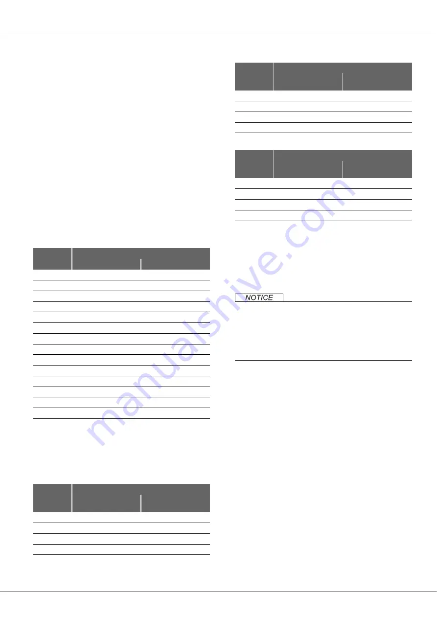
Pump Size
Clearance FPS in mm
Impeller / pump cover
Impeller / casing
(calculated)
711/712
0,5
(5,5)
721/722
0,5
(5,5)
741/742
0,5
(5,5)
751/752
1.0
(5,0)
Table 7 Clearances in model S
3521/3522
0,5
(10,5)
3531/3532
0,5
(11)
3541/3542
1,0
(11)
3551/3552
1,0
(11)
Pump Size
Clearance FPR in mm
Impeller / pump cover
(calculated)
Impeller / casing
3521/3522
(10,5)
0,5
3531/3532
(11)
0,5
3541/3542
(11)
1,0
3551/3552
(11)
1,0
Table 8 Clearances in model R
Pump Size
Clearance FPS in mm
Impeller / pump cover
Impeller / casing
(calculated)
Table 7 Clearances in model S
Содержание FP
Страница 1: ...Original Instructions Assembly Instructions Centrifugal Pump FP Series Pump Type Pump No ...
Страница 32: ... FP PUMP SERIES 32 940 Key 941 Woodruff key 950 spring Part Number Name ...
Страница 37: ...37 ...
Страница 38: ... FP PUMP SERIES 38 ...
Страница 39: ...39 ...