background image

03

WARNING

CAUTION

•  Servicing shall only be performed as recommended by the equipment manufacturer. Maintenance and repair 

requiring the assistance of other skilled personnel shall be carried out under the supervision of the person 

competent in the use of flammable refrigerants.

•  Tear apart and throw away plastic packaging bags so that children will not play with them.Children playing with 

plastic bags face danger.

•  Safely dispose of packing materials such as nails and other metal or wood parts that could cause injuries.
•  Ask your dealer or qualified personnel to perform installation work in accordance with this manual. Do not install 

the unit yourself. Improper installation could result in water leakage, electric shocks or fire.

•  Be sure to use only specified accessories and parts for installation work. Failure to use specified parts may 

result in water leakage, electric shocks, fire, or the unit falling from its mount.

•  Install the unit on a foundation that can withstand its weight. Insufficient physical strength may cause the 

equipment to fall and possible injury.

•  Perform specified installation work with full consideration of strong wind, hurricanes, or earthquakes. Improper 

installation work may result in accidents due to equipment falling.

•  Make certain that all electrical work is carried out by qualified personnel according to the local laws and 

regulations and this manual using a separate circuit. Insufficient capacity of the power supply circuit or improper 

electrical construction may lead to electric shocks or fire.

•  Be sure to install a ground fault circuit interrupter according to local laws and regulations. Failure to install a 

ground fault circuit interrupter may cause electric shocks and fire.

•  Make sure all wiring is secure. Use the specified wires and ensure that terminal connections or wires are 

protected from water and other adverse external forces. Incomplete connection or affixing may cause a fire.

•  When wiring the power supply, form the wires so that the front panel can be securely fastened. If the front panel 

is not in place there could be overheating of the terminals, electric shocks or fire.

•  After completing the installation work, check to make sure that there is no refrigerant leakage.
•  Never directly touch any leaking refrigerant as it could cause severe frostbite.Do not touch the refrigerant pipes 

during and immediately after operation as the refrigerant pipes may be hot or cold, depending on the condition 

of the refrigerant flowing through the refrigerant piping, compressor and other refrigerant cycle parts. Burns or 

frostbite are possible if you touch the refrigerant pipes. To avoid injury, give the pipes time to return to normal 

temperature or, if you must touch them, be sure to wear protective gloves.

•  Do not touch the internal parts (pump, backup heater, etc.) during and immediately after operation. Touching the 

internal parts can cause burns. To avoid injury, give the internal parts time to return to normal temperature or, if 

you must touch them, be sure to wear protective gloves.

•  Do not use means to accelerate the defrosting process or to clean, other 

than those recommended by the manufacture.

•  The appliance shall be stored in a room without continuously operating 

ignition sources (for example: open flames, an operating gas appliance or 

an operation electric heater.) 

•  Do not pierce or burn.
•  Be aware that refrigerants may not contain an adour.

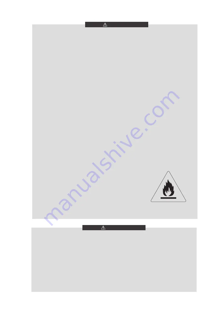
Caution: Risk of fire/ 

flammable materials

•  Ground the unit.
•  Grounding resistance should be according to local laws and regulations.
•  Do not connect the ground wire to gas or water pipes, lightning conductors or telephone ground wires. Incomplete 

grounding may cause electric shocks.
- Gas pipes

Fire or an explosion might occur if the gas leaks.

- Water pipes: Hard vinyl tubes are not effective grounds.
- Lightning conductors or telephone ground wires: Electrical threshold may rise abnormally if struck by a lightning 

bolt.

•  Install the power wire at least 3 feet (1 meter) away from televisions or radios to prevent interference or noise. 

(Depending on the radio waves, a distance of 3 feet (1 meter) may not be sufficient to eliminate the noise.) 

•  Do not wash the unit. This may cause electric shocks or fire. The appliance must be installed in accordance with 

national wiring regulations. If the supply cord is damaged, it must be replaced by the manufacturer, its service 

agent or similarly qualified persons in order to avoid a hazard.

Содержание Kaysun KEM-30 DRS4

Страница 1: ...you very much for purchasing our air conditioner Before using your air conditioner please read this manual carefully and keep it for future reference KEM 30 DRS4 KEM 60 DRS4 OWNER S INSTALLATION MANU...

Страница 2: ...on 08 6 4 Installation of damping devices 08 6 5 Installation of device to prevent snow build up and strong breeze 09 7 CONNECTION DRAWING OF PIPELINE SYSTEM 10 8 OVERVIEW OF THE UNIT 8 1 Main parts o...

Страница 3: ...irst startup after shutdown 33 11 8 Refrigeration system 33 11 9 Disassembling compressor 33 11 10 Auxiliary electric heater 33 11 11 System antifreezing 33 11 12 Replacement of safety valve 34 11 13...

Страница 4: ......

Страница 5: ...power supply is 380 415V 3N 50Hz the minimum allowable voltage is 342V and the maximum voltage is 456V 2 To maintain better performance please operate the unit under the following outdoor temperature...

Страница 6: ...s also used to alert against unsafe practices Indicates situations that could only result in accidental equipment or property damage Explanation of symbols displayed on the indoor unit or outdoor unit...

Страница 7: ...ls electric shocks or fire After completing the installation work check to make sure that there is no refrigerant leakage Never directly touch any leaking refrigerant as it could cause severe frostbit...

Страница 8: ...ans in accordance with national wiring regulation and this circuit diagram An all pole disconnection device which has at least 3mm separation distance in all pole and a residual current device RCD wit...

Страница 9: ...and copper pipes 4 If the unit is within the reach of unauthorized personnel take protective measures for safety considerations such as installing a fence These measures can prevent man caused or acci...

Страница 10: ...ine dimensional of KEM 30 DRS4 6 1 2 KEM 60 DRS4 B Left view Front view E D F A C Top view Fig 6 2 Outline dimensional of KEM 60 DRS4 Table 6 1 Model KEM 30 DRS4 KEM 60 DRS4 A 1870 2220 B 1000 1325 C...

Страница 11: ...rsian blinds are required the total loss of static pressure should be less than the static pressure outside the fan The space between the unit and sunk fence or Persian blinds should also meet the req...

Страница 12: ...is directed away from roadways and footpaths especially in locations where the climate is such that condensate may freeze unit mm Drainage channel Anchor bolt Inlet and outlet pipe side Electric cont...

Страница 13: ...w 1 Measures to prevent build up of snow The base height should be as least the same as the predicted snow depth in the local area Outdoor unit Base height Fig 6 10 Snow prevention base height 2 Light...

Страница 14: ...ain valve Two way valve Three way valve Terminal Auxiliary electric heater unit unit Y type filter requiring 40 meshes unit Fig 7 1 Connection drawing of pipeline system 8 OVERVIEW OF THE UNIT 8 1 Mai...

Страница 15: ...r 1 Door 2 Door 3 Door 4 Fig 8 3 Doors of KEM 30 DRS4 Door 1 give access to the compartment of water pipes and water side heat exchanger Door 2 3 4 give access to the hydraulic compartment and electri...

Страница 16: ...sure switch 28 Fast oil return solenoid valve 7 Oil separator 29 Low pressure switch 8 4 way valve 30 Filter 9 System pressure sensor 31 Capillary 10 DC fan 32 Outdoor ambient temperature sensor 11 Co...

Страница 17: ...erature control switch 1 33 Suction temperature sensor 8 Discharge temperature control switch 2 34 Low pressure switch 9 One way valve1 35 Filter 10 One way valve2 36 Capillary 11 High pressure switch...

Страница 18: ...ted only in the early period after the power supply is connected and they are not detected while the unit is in operation 2 CN12 Quick return oil solenoid valve 3 CN5 EVA HEAT Water side heat exchange...

Страница 19: ...erature sensor of the condenser T5 water tank temperature sensor T6A Refrigerant inlet temperature of EVI plate heat exchanger T6B Refrigerant inlet temperature of EVI plate heat exchanger 24 CN16 Sys...

Страница 20: ...ntrol valid for S12 2 ON S12 3 Normal cooling mode valid for S12 3 OFF factory default Low temperature cooling valid for S12 3 ON 41 CN7 TEMP SW Target water temperature switching port 42 ENC2 POWER D...

Страница 21: ...nnecting the power supply Please carefully read the labels on the electric cabinet The user s attempt to repair the controller is prohibited since improper repair may cause electric shock damages to t...

Страница 22: ...Electrical wiring precaution c d Power wiring must be entrusted to professionals with electrician qualification Fig 8 9 4 Electrical wiring precaution d 8 5 5 Power supply specification Table 8 6 Ite...

Страница 23: ...current Grounding 3 Grounding 2 Grounding 1 Grounding wire Lightning arrester Power distribution transformer Manual switch Fuses Power 380 415V 3N 50Hz Unit Fig 8 10 Requirements of power supply wirin...

Страница 24: ...to monitor the state of com pressor When the compressor is operating the light will be powered on The wiring of water pump and pipeline auxiliary heater and ac light of the state of compressor is as...

Страница 25: ...o the ALARM ports of the module units as follows electric control box ALARM port Device provided by user Fig 8 16 Wiring of ALARM port If the unit is operating unnormally the ALARM port is closed othe...

Страница 26: ...ry heater according to the actual parameter of products and national Contactor Contactor Power Transformer AC220 240V AC 8 5 V CN2 CN60 IRU SLSHOLQH CN74 CN61 0 1 21752 5 21752 5 CN60 CN74 CN61 5 5 5...

Страница 27: ...0V AC 8 5 V CN2 CN60 IRU SLSHOLQH CN74 CN61 0 1 21752 5 21752 5 CN60 CN74 CN61 5 5 5 5 021 725 5 21752 5 CN60 CN74 CN61 5 5 5 5 021 725 5 21752 5 7 7 20 7 X Y X Y X Y 203 67 7 3803 1 CN83 7 CN30 7 7 C...

Страница 28: ...chased by the user k All low positions of the water system should be provided with drainage ports to drain water in the evaporator and the system completely and all high positions should be supplied w...

Страница 29: ...c 1 1 4 KEM 60 DRS4 Hoop connection DN50 Fig 8 20 connection mode of KEM 30 DRS4 pipe Fig 8 21 connection mode of KEM 60 DRS4 pipe 8 6 3 Design of the store tank in the system kW is the unit for cooli...

Страница 30: ...water resistance h2 Pump water resistance h3 Water resistance of the longest water loop distance includes pipe resistance different valve s resistance flexible pipe resistance pipe elbow and three way...

Страница 31: ...24 Installation of multi module no more than 16 modules 2 Table of diameter parameters of main inlet and outlet pipes Table 8 10 Cooling capacity Total inlet and outlet water pipe inside nominal diam...

Страница 32: ...up at low outdoor ambient temperatures During initial start up and when water temperature is low it is important that the water is heated gradually Failure to do so may result in concrete floors crack...

Страница 33: ...a fault code If a fault occurs remove the fault first and start the unit according to the operating method in the unit control instruction after determining that there is no fault existing in the unit...

Страница 34: ...A system discharge temperature sensorfailure Recovered upon error recovery 2Ed B system discharge temperature sensor failure Recovered upon error recovery 16 EF Unit water return temperature sensor fa...

Страница 35: ...system B 68 F7 Not insert electronic expansion valve Recovered by power off 70 xF9 Inverter module temperature sensor error x 1 means Tfin1 x 2 means Tfin2 72 Fb Pressure sensor error Recovered upon...

Страница 36: ...nt air conditioner errors which bring inconvenience to your life and work 2 Maintenance of main parts Close attention should be paid to the discharge and suction pressure during the running process Fi...

Страница 37: ...d water circulate and start up unit and make the low pressure control switch short circuit if necessary Slowly inject refrigerant into the system and check suction and discharge pressure 11 9 Disassem...

Страница 38: ...et of safty valve 7 8 UNF Fig 11 1 Replacement of safety valve WARNING The air outlet of safety valve must be connected to the appropriate pipe which can direct the leaking refrigerant to the appropri...

Страница 39: ...ately ventilated before breaking into the system or conducting any hot work A degree of ventilation shall continue during the period that the work is carried out The ventilation should safely disperse...

Страница 40: ...detection fluids are suitable for use with most refrigerants but the use of detergents containing chlorine shall be avoided as the chlorine may react with the refrigerant and corrode the copper pipe...

Страница 41: ...oning it is recommended good practice that all refrigerants are removed safely When transferring refrigerant into cylinders ensure that only appropriate refrigerant recovery cylinders are employed Ens...

Страница 42: ...pressure 5 Check running current 6 Whether unit has been through refrigerant leakage test 7 Whether there is noise on all the panels ofunit 8 Check whether the main power source connection iscorrect R...

Страница 43: ...ressure switch freeze proof device water flow volume controller Overcurrent device power phase sequence device etc Refrigerant Type R 32 Water pipe system Charging volume kg 7 9 14 0 Waterflow volume...

Страница 44: ...0 Tj 25 C Pdc 13 15 kW Tj 25 C EERd 5 35 Tj 20 C Pdc 6 58 kW Tj 20 C EERd 6 90 Degradation co efficient for chillers Cdc 0 90 Power consumption in modes other than active mode Off mode POFF 0 02 kW Cr...

Страница 45: ...3 86 kW Tj 25 C EERd 4 50 Tj 20 C Pdc 11 72 kW Tj 20 C EERd 5 04 Degradation co efficient for chillers Cdc 0 9 Power consumption in modes other than active mode Off mode POFF 0 030 kW Crankcase heater...

Страница 46: ...operating limit temperature WTOL C Cycling interval capacity for heating at Tj 2 C Pcych kW Cycling interval efficiency at Tj 7 C COPcyc Degradation coefficient 4 at T 2 C Cdh Cycling interval capacit...

Страница 47: ...t T 7 C Cdh Heating water operating limit temperature WTOL C Cycling interval capacity for heating at Tj 2 C Pcych kW Degradation coefficient 4 at T 2 C Cdh Cycling interval efficiency at Tj 7 C COPcy...

Страница 48: ......

Отзывы: