S70-101SM
Page 20
Frick XJS and XJF Rotary Screw Compressor
Service Manual
DISHCHARGE
BALL BEARING
INSTALLATION
TOOL
ROLLER
BEARING
DISCHARGE
CASING
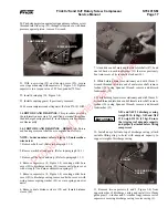
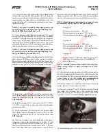
8. Place discharge casing, with flange down, on work surface
and install two o-rings (23) and gas seals (24) in casing.
Ensure that spring pin (6, Figure 1-4) in each gas seal engages
oil hole (bore) in discharge casing.
GAS SEAL
O-RING
DISCHARGE
CASING
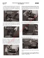
9. Using Discharge Ball Bearing Installation Tool, install new
roller bearing (25) into each bore in discharge casing.
10. Rebalance rotors* if possible. Install male rotor into rotor
casing, with threaded end of rotor facing discharge end of
compressor. Ensure that all parts have been thoroughly cleaned
with OSHA approved, nonflammable degreaser and coated
with a thin film of clean refrigerant oil.
* Balancing specifications:
95mm male
.036 in.-oz.
95mm female
.028 in.-oz.
120mm male
.072 in.-oz.
120mm female
.055 in.-oz.
11. Install female rotor into rotor casing, with threaded end of
rotor facing discharge end of compressor. Ensure that all parts
have been thoroughly cleaned with OSHA approved, non-
flammable degreaser and coated with a thin film of clean
refrigerant oil.
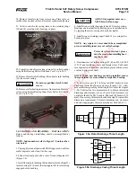
12. Place new o-ring (45) in groove in discharge end of rotor
casing; apply a light coating of grease to keep o-ring in place.
Align discharge casing with rotor casing, ensuring that dowel
pins (46 and 58) engage dowel pin holes; secure discharge
casing with four capscrews (1 and 5, Figure 1-4) evenly
spaced around casing flange. Tighten capscrews to a torque
value of 58 foot-pounds (79 Nm).
NOTE: If air tool is not available, a 12 mm "T" handle
can be used to pull and push rotors.
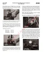
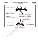
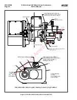
13. Connect Air Cylinder Tool to drive end of compressor.
Thread two 12mm guide pins (3
1
/
2
-
inches long for male
COMPRESSOR
DISCHARGE END
MALE ROTOR GUIDE PIN
MEASURING
ROTOR-TO-CASING
CLEARANCE
rotor and 5
1
/
2
-inches long for female rotor) into discharge end
of rotor shafts. Set up a dial indicator at discharge end of
compressor, with indicator resting against end of male rotor
guide pin. Using Air Cylinder Tool, with pressure set 100 psi
max. male side – 100 psi max. female side, pull rotor back and
set indicator to zero. Push shaft forward and record measure-
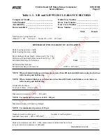
ment (refer to Table 1.1). Repeat procedure for female rotor.
Rotor-to-casing clearance should be .025-inch to .031-inch. If
rotor-to-casing clearance is greater than .031, look for a
binding o-ring between rotor casing and discharge casing
flanges, or metal or dirt contamination between flanges.
COMPRESSOR
DRIVE END
AIR CYLINDER
TOOL
Property of American Airlines


