S70-101SM
Page 16
Frick XJS and XJF Rotary Screw Compressor
Service Manual
18. If previously removed, install o-rings (11 and 29) and
glyd-rings (10 and 28) on stepper piston (27). To install
glyd-ring, heat to 250
×
F (121
×
C) for one hour
and push into
slot. Use a 4-inch (10 cm) hose clamp, with solid shim
material in I.D., to hold glyd-rings in place for 10 minutes.
19. Place slide stop piston inside stepper piston. Thread 8mm
T-wrench into stepper piston; install stepper piston and slide
stop piston in compressor.
5. Insert 10M x 1.5 capscrew (20, Figure 1-4) into slide valve
piston; insert assembly into discharge housing and tighten capscrew.
6. Before fully tightening capscrew, push slide valve piston
into bore, so that glyd-rings are positioned within bore area;
tighten capscrew to a torque value of 30
foot-pounds (41 Nm).
7. Using handle of a rubber mallet, push piston into bore until it
stops, allowing spring to push piston out. Repeat this step 10-15
times to ensure piston moves back and forth freely. If piston does
not move freely, loosen capscrew and rotate piston within bore
90 degrees; tighten capscrew and recheck piston for freedom of
movement. Repeat step as required until piston moves freely.
Apply a small amount of Loctite on cap screw threads.
8. Install new o-ring (18), internal check valve (17), with
conical end facing outboard, and check valve retainer (16) in
slide valve piston (19).
SLIDE VALVE PISTON
11. Install unloader spring (22), spring support (23), and slide
stop (25). Thread 8mm T-wrench into slide stop, pushing slide
stop against spring force. With finger through oil drain hole,
push in against spring force and feel along bottom of slide
stop. When threaded hole in slide stop is located, insert an
8mm screw (Frick p/n 111Q0740796) through oil drain hole
and thread into slide stop.
9. If previously removed, install o-ring (11) and glyd-rings (10
and 15) on slide valve piston. To install glyd-ring, heat to
250
×
F (121
×
C) and push into slot. Use a 4-inch (10 cm) hose
clamp to hold glyd-rings in place for 10 minutes.
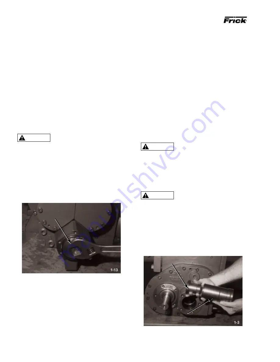
10. For old style piston: Through drive end of compressor,
apply pressure to slide valve with handle of rubber mallet and
install slide valve piston into discharge end of compressor.
Thread piston into slide valve; tighten by using 1
1
/
4
-inch
wrench on flats located on end of slide valve piston.
12. Using handle of rubber mallet, push in on end of slide valve
piston against spring ; release pressure several times to ensure
that slide valve and slide valve piston “slide” smoothly. If piston
does not move smoothly, look for a problem or defect with glyd-
ring.
13. Place new o-ring (12) on cylinder cover (14); secure cyl-
inder cover to discharge casing (7) with capscrews (8). Tighten
capscrews to a torque value of 18 foot-pounds (24.5 Nm).
14. Connect
1
/
4
-
inch capacity control oil line to connector
located on cylinder cover.
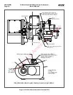
15. Install new o-rings (2 and 3, Figure 1-5) on rod guide (5,
Figure 1-5). Install indicator rod spring (4, Figure 1-5) and
indicator rod (6, Figure 1-5) into rod guide; thread rod guide
into discharge casing (9).
16. Install compressor slide valve indicator position switch
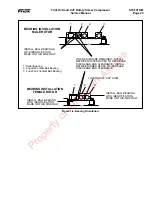
and slide valve indicator position switch cover.
SLIDE STOP PISTON
STEPPER PISTON
Protective, heat-resistant gloves must
be worn when installing glyd-rings.
17. If previously removed, install o-ring (11) and glyd-ring
(10) on slide stop piston (26). To install glyd-ring, heat to
250
×
F (121
×
C) for one hour and push into slot. Use a 4-inch
(10 cm) hose clamp, with solid shim material in I.D., to hold
glyd-rings in place for 10 minutes.
Protective, heat-resistant gloves must
be worn when installing glyd-rings.
Protective, heat-resistant gloves must
be worn when installing glyd-rings.
WARNING
WARNING
WARNING
Property of American Airlines


