S70-101SM
Page 17
Frick XJS and XJF Rotary Screw Compressor
Service Manual
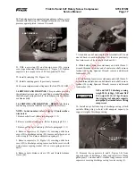
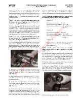
20. Push stepper piston against spring and remove 8mm screw
threaded into slide stop (25), through oil drain hole; with hand
pressure against piston, remove T-wrench.
STEPPER PISTON
8MM T-WRENCH
21. With new o-ring (32) on slide stop cover (30), secure
cover to gear housing with capscrews (7, Figure 1-2). Tighten
capscrews to a torque value of 58 foot-pounds (79 Nm).
22. Install drain plug (24, Figure 1-4).
23. Install coupling guard, if previously removed.
24. Evacuate compressor and oil separator. (Refer to S70-101 IOM.)
1.4 ROTORS AND BEARINGS. This procedure provides
the information necessary for qualified personnel to replace
the discharge bearing assembly, including required compres-
sor disassembly.
1.4.1 ROTORS AND BEARINGS – REMOVAL. Rotors
and bearings removal shall be accomplished as follows:
NOTE:
Index numbers refer to Figure 1-2, unless other-
wise noted.
1. Remove shaft seal. (Refer to paragraph 1.1.2)
2. Remove jackshaft and gears. (Refer to paragraph 1.2.1)
3. Remove slide valve and stop. (Refer to paragraph 1.3.1)
4. Remove capscrews (8, Figure 1-4) securing outlet bore
cover (39) to discharge casing (43); remove outlet bore cover
with o-ring (27) and nine compression springs (37).
5. Remove capscrews (8, Figure 1-4) securing outlet bore
cover (41) to discharge casing; remove outlet bore cover with
o-ring; remove spring washer (42), or wave spring on newer
units.
6. Remove male distance sleeve (38) and female distance
sleeve (44).
7. At nondrive end of male and female rotor shafts (47), bend
one tab back on each lockwasher (35) that was previously
bent into recess of its respective locknut (36).
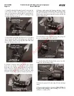
8. While holding male rotor stationary and with 12mm T-
wrench threaded into drive end of male rotor shaft, remove
locknut (36) using Spanner Wrench; remove and discard
lockwasher (35).
9. While holding female rotor stationary and with 12mm T-
wrench threaded into drive end of female rotor shaft, remove
locknut (36) using Spanner Wrench; remove and discard
lockwasher (35).
11. Remove two capscrews (1 and 5, Figure 1-4) from
opposite sides of discharge casing and install two 12mm
guide pins (3
1
/
2
-inches and 5
1
/
2
-inches long); remove rest of
capscrews securing discharge casing to rotor casing (3).
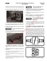
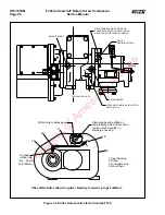
10. Install an eyebolt into top of discharge casing; attach
suitable lifting sling to hoist with adequate capacity to
support weight of discharge casing.
EYEBOLT
D I S C H A R G E
CASING
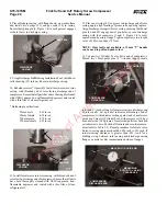
XJS and XJF 95 discharge casing
weigh 90 lb. (41kg); XJS and XJF
120 weigh 115 lb. (53 kg). Ensure
that rigging is of adequate capacity
and properly attached before lifting
compressor.
WARNING
Property of American Airlines


