S70-101SM
Page 9
Frick XJS and XJF Rotary Screw Compressor
Service Manual
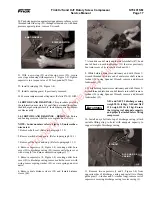
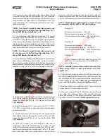
Figure 1-3. Using Clamp Collar Installation Tool.
1.2 JACKSHAFT AND GEARS. This procedure provides the
information necessary for qualified personnel to replace the
jackshaft bearings, including required compressor disassembly.
1.2.1 JACKSHAFT AND GEARS – REMOVAL. Jackshaft
removal shall be accomplished as follows:
NOTE: Index numbers refer to Figure 1-2, unless other-
wise noted.
1. Place suitable drain pan under compressor oil drain, remove
drain plug located at the center bottom on the gear cover and
drain plug (24, Figure 1-4).
2. Remove shaft seal. (Refer to paragraph 1.1.2.)
3. Place suitable drain pan under slide stop cover (30, Figure
1-4) and remove capscrews (7) securing slide stop cover to
gear cover (2, Figure 1-4); remove slide stop cover and o-ring
(32, Figure 1-4), while holding stepper piston in by hand.
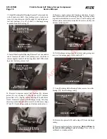
8MM T-WRENCH
STEPPER PISTON
5. Remove stepper piston with glyd-rings (10 and 28, Figure
1-4) and o-rings (11 and 29, Figure 1-4). If glyd-rings and o-
rings are to be replaced, cut glyd-rings off of stepper piston
using knife and remove and discard o-rings.
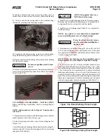
4. Thread 8mm T-wrench into stepper piston and push piston
in against spring force. With finger through oil drain hole (24,
STEPPER PISTON
Figure 1-4), push in against spring force and feel along bottom
of slide stop. When threaded hole in slide stop is located, insert
8mm screw (Frick p/n 111Q0740796) through oil drain hole
and thread into slide stop.
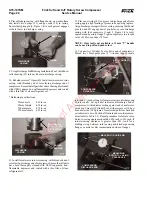
4
2
1
13
12
10
9
8
7
3
5
6
11
1. O-Ring
2. Carbon Face
3. Rotating Seal Seat Assembly
with shiny side of seat facing outward
4. O-Ring
5. Gear Cover
6. Four-Point Contact Ball Bearing
7. Clamp Collar Installation Tool
8. Shaft
9. Clamp Collar
10. Seal Seat Backup Ring
11. Seal Housing
12. Carbon Faced Seal Assembly
13. Strainer
Property of American Airlines


