Frick Vyper 254 Скачать руководство пользователя страница 54

VYPER

 VARIABLE SPEED DRIVE

MAINTENANCE

100-200 IOM (FEB 09)

Page 54

internal temperature sensors (5K ohm at 25°C) to monitor 

their  baseplate  temperature. The  inverter  power  module 

baseplate temperatures shall be compared in software to a 

lower limit of 37°F (2.8°C) and if this limit is exceeded the 

unit shall initiate a cycling shutdown. In addition, if the three 

Inverter baseplates and the Converter heat sink temperature 

falls below the 37°F limit, the unit shall trip and the fan(s) 

and water pump shall also be energized. This feature shall 

provide  the  Service  Dept.  with  a  means  to  run  the  water 

pump while filling the cooling system (by pulling VSD logic 

board plug P2).

 Fault 14:  low Phase C Inverter Baseplate Temperature

Message

Quantum: “Fault 14”

Quantum LX: “Low Phase C Inverter Base plate Temperature”

Same comments as Fault 13 except applying to Phase C 

Inverter Base plate Temperature

Fault 17:  High Phase A Instantaneous Current

Message

Quantum: “Fault 17”

Quantum LX: “VSD High Phase A Instantaneous Current”

The three output lines to the motor are monitored via three 

current transformers within the drive. The unit’s three phases 

of instantaneous output current are compared to a prescribed 

limit which is contained in hardware. If the peak current limit 

is exceeded, the unit will trip and the Quantum

LX Panel will 

display a fault message. 

The Vyper

  Logic  board  generates  this  shutdown.  If  any 

one  phase  of  motor  current,  as  measured  by  the  Output 

Current Transformers, exceeds 771 Amps peak for 305 HP 

/ 1200 Amps peak for 437 HP, a shutdown will occur. If an 

Instantaneous  Current  occurs,  but  the  chiller  restarts  and 

runs without a problem, the cause may be attributed to a 

voltage sag on the utility power feeding the Vyper

 that is in 

excess of the specified dip voltage for this product. This is 

especially true if the chiller was running at or near full load. 

If there should be a sudden dip in line voltage, the current 

to  the  motor  will  increase,  since  the  motor  wants  to  draw 

constant  horsepower. This  is  a  common  problem  when  a 

second chiller is started. Contact Frick factory service if this 

is confirmed to be a problem.

Fault 18:  High Phase B Instantaneous Current

Message

Quantum: “Fault 18”

Quantum LX: “: “VSD High Phase B Instantaneous Current”

Same comments as Fault 17 except applying to Phase B 

Instantaneous Current

  Fault 19:  High Phase C Instantaneous Current

Message

Quantum: “Fault 19”

Quantum LX: “VSD High Phase C Instantaneous Current”

Same comments as Fault 17 except applying to Phase C 

Instantaneous Current

 Fault 21:  Vyper Phase A Gate Driver

Message

Quantum: “Fault 21”

Quantum LX: “VSD Phase A Gate Driver Fault”

The  unit’s  phase  bank  assembly  shall  contain  one  IGBT 

gate driver control board. This board monitors the satura-

tion voltage drop across each IGBT while gated on. If the 

IGBT’s saturation voltage exceeds the prescribed limit, the 

gate driver will make the determination that a short circuit 

is present. This in turn shall cause the unit to trip and the 

Quantum

LX Panel shall display the message Fault 21. If the 

driver board’s power supply voltage falls below the permis-

sible limit, this same message shall be generated.

A second level of overcurrent protection exists on the Vyper


gate driver board. The collector-to-emitter voltage of each 

IGBT  is  checked  continuously  while  the  device  is  being 

turned on. This is also called the collector-to-emitter satura-

tion voltage. If the voltage across the IGBT is greater than a 

set threshold, the IGBT is turned off and a shutdown pulse 

is sent to the Vyper

 logic board shutting down the entire 

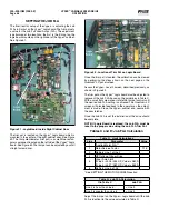
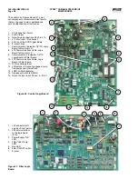
system. To diagnose the problem, first check the LED’s on 

the gate driver board of the Vyper

 power unit. Usually one 

of the six LED’s will be out. This clearly points to a bad gate 

driver, and requires replacement of the Vyper

 power module. 

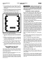
If all LED’s are lit, and the problem repeatedly occurs in one 

phase, swap all three pole cables at the logic board J8, J9, 

and J10. Plug J8 into J9, J9 into J10, and J10 into J8. If the 

display now reports a trip in a different phase, the problem 

is either in the Vyper

 power module or gate driver board, or 

in the cable that feeds the gate driver board from the Vyper


Logic board. The fault could also be cause by a problem in 

the drive line. Ensure that the compressor is free to rotate. 

If  the  display  continues  to  report  a  gate  driver  FLT  in  the 

same phase, even with cables swapped, the problem is in the 

Vyper

 Logic board. Once you have finished troubleshooting, 

be sure to put all of the cables back into their original mating 

connectors. Also, be aware that a gate driver fault can be 

initiated when the Vyper

 is not running if a power supply 

has failed on the gate driver board.

Check that the LRA rating of the motor is not higher than the 

LRA rating of the drive.

 Fault 22:  Vyper Phase B Gate Driver

Message

Quantum: “Fault 22”

Quantum LX: “VSD Phase B Gate Driver Fault”

Same comments as Fault 21 except applying to Phase B 

Gate Driver.

 Fault 23:  Vyper Phase C Gate Driver

Message

Quantum: “Fault 23”

Quantum LX: “VSD Phase C Gate Driver Fault”

Same comments as Fault 21 except applying to Phase C 

Gate Driver.

 Fault 24:  Vyper Single Phase Input Power

Message

Quantum: “Fault 24”

Quantum LX: “VSD Single Phase Input Power Fault”

The Vyper’s SCR Trigger Control board contains circuitry that 

checks the three-phase mains for the presence of all three 

line voltages. If all line voltages are not present, the unit will 

trip  and  the  Quantum

LX  Panel  will  display  the  message 

Fault 24. 

This shutdown is generated by the SCR Trigger board and 

relayed to the Vyper

 Logic board to initiate a system shut-

Содержание Vyper 254

Страница 1: ...3c THIS MANUAL CONTAINS RIGGING ASSEMBLY START UP AND MAINTENANCE INSTRUCTIONS READ THOROUGHLY BEFORE BEGINNING INSTALLATION FAILURE TO FOLLOW THESE INSTRUCTIONS COULD RESULT IN DAMAGE OR IMPROPER OPE...

Страница 2: ...IPMENT 11 INTERFERENCE WITH ELECTRONIC EQUIPMENT 12 SYSTEM OPERATING CONDITIONS 12 PNEUMATIC CONTROLS 12 VYPER SYSTEM OVERVIEW 12 CONFIGURATION 16 VYPER COOLING LOOP 16 Liquid Cooled Vyper P I Diagram...

Страница 3: ...ctronic con trol equipment All safety precautions consistent with opera tion of high current and voltage electrical equipment should be strictly enforced JOB INSPECTION Immediately upon arrival examin...

Страница 4: ...GING AND HANDLING The Vyper cabinet unit is best moved via lifting lugs on the top sides of the cabinet Special care must be exercised not to damage the pump or peripheral equipment on the rear of the...

Страница 5: ...and Frick publication S90 400 SB Verify that all control power 120 VAC communications analog wiring and 460 VAC power are in separate metallic con duits Properly shielded and grounded analog cables a...

Страница 6: ...e the tables in this manual to calculate what they should be 7 Verify proper operation of the motorized coolant mixing valve on the back of the drive Locate the Coolant mixing valve on the back of the...

Страница 7: ...operating frequency range of the drive The unit is started with the compressor fully unloaded until the frequency reaches the minimum operating frequency range In addition the drive is capable of ope...

Страница 8: ...0 feet Adequate service clearances including door swing must be maintained around the Vyper Care should be taken to ensure that the Vyper and it s associated piping and wiring do not obstruct the acce...

Страница 9: ...ER PRESSURE DROP In order to adequately size piping and booster pump require ments the pressure drop of the coolant across the heat Figure 3 Minimum Flow Rates GLYCOL exchanger must be known Figure 4...

Страница 10: ...tions regarding disconnect devices conductor sizes wire types and circuit protection Unshielded cable is acceptable if it can be separated from sensitive circuitry Allow a spacing of 12 inches for eve...

Страница 11: ...r at all operational loads and conditions Capacitors can be located at one or several places on a distribution system Solid state motor controllers may not run or have difficulty starting in that scen...

Страница 12: ...odes One SCR and one diode are contained in each module Three modules are required to covert the three phase input AC voltage to DC voltage 1SCR 3SCR The modules are mounted on a liquid cooled heatsin...

Страница 13: ...SPEED DRIVE INSTALLATION 100 200 IOM FEB 09 Page 13 Figure 6 Vyper Elementary Wiring Diagram NOTE Drawings for specific units can be found in the door of the Vyper drive or check with Frick Engineeri...

Страница 14: ...sure that the IGBT transistor module does not rupture if a failure were to occur on the DC link of the Filter Power Unit THETHREE PHASE INDUCTOR provides some impedance for the filter to work against...

Страница 15: ...VYPER VARIABLE SPEED DRIVE INSTALLATION 100 200 IOM FEB 09 Page 15 Figure 8 Harmonic Filter Elementary Wiring Diagram NOTE Typical Check with engineering for latest drawings...

Страница 16: ...nd shutdowns as sociated with theVyper coolant temperature reading These wil also be factory set for a Low Temp alarm and shutdown at 85 F and 80 F with a 90 second delay when running The High Temp Al...

Страница 17: ...VYPER VARIABLE SPEED DRIVE INSTALLATION 100 200 IOM FEB 09 Page 17 Liquid Cooled Vyper P I Diagram Economized...

Страница 18: ...VYPER VARIABLE SPEED DRIVE INSTALLATION 100 200 IOM FEB 09 Page 18 Liquid Cooled Vyper P I Diagram Noneconomized...

Страница 19: ...The Vyper cabinet is mounted on a rectangular welded steel channel which provides both an attachment point for the cabinet s side brackets and also helps to maintain the rigidity of the cabinet durin...

Страница 20: ...Page 20 BLOWER MOTOR ROTATION The Blower Motor rotation is marked on the blower assembly and is to be such that the blower draws into the assemly through the screen and pushes down and through the mot...

Страница 21: ...Page 21 Dimensions in Inches Drive HP A B C D E F G H J K 305 254 1 63 4 50 9 00 6 38 4 38 35 00 5 50 3 56 6 63 2 00 437 362 6 63 6 75 10 13 2 00 3 25 40 53 2 25 3 00 13 00 2 00 Contact factory for de...

Страница 22: ...in that the Drive has been powered down for at least five minutes This allows the internal capacitors resistors to discharge the DC bus and allow for safe maintenance of the unit Failure to do so may...

Страница 23: ...ion 216 240 in lb ELECTRICAL CONDUITS All power wiring must be contained in metallic conduit All compressor motor wiring must be in a separate metallic conduit Oil pump motor wiring must be in a separ...

Страница 24: ...VYPER VARIABLE SPEED DRIVE INSTALLATION 100 200 IOM FEB 09 Page 24 MOTOR RTD THERMAL PROTECTION Figure 17 TEMPERATURE CONTROL VALVE WIRING Figure 18...

Страница 25: ...VYPER VARIABLE SPEED DRIVE INSTALLATION 100 200 IOM FEB 09 Page 25 MOTOR COOLING BLOWER WIRING Figure 19 Figure 20 DRAWING NOTES...

Страница 26: ...VYPER VARIABLE SPEED DRIVE INSTALLATION 100 200 IOM FEB 09 Page 26 ANALOG BOARD WIRING Figure 21...

Страница 27: ...ans c Confirm operation of coolant circulation pump d Confirm wiring and operation of the motor blower fans if present Mounting a Verify that the Vyper Drive is properly mounted to the floor or wall f...

Страница 28: ...proper electrical connections as discussed in previous sections The Vyper setup consists of three primary requirements Cooling Loop Fluid Preparation Quantum LX Panel Setup Job FLA Trim Pot Adjustment...

Страница 29: ...ntil the fluid level remains constant about one inch form the top of the manifold See Figure 30 Figure 30 Step 6 Top Off the Cooling System Figure 31 Step 7 Replace the Pipe Plug and Tighten Step 7 Re...

Страница 30: ...fferential pressure the motor speed will increase to meet the capacity requirement When the slide valve reaches the Capacity Control Slide Valve setpoint the motor speed can increase At this point the...

Страница 31: ...r can select either the Vyper or the Har monic Filter setup screens See Figure 35 The flydown menu allows the user to select either theVyper Drive setup or if the Harmonic Filter is installed the disp...

Страница 32: ...aring theVSD memory and resetting the kWh record Standby Time The VSD enters Standby mode when there is no load on the VSD The VSD capacitor banks remain charged and the compressor output is 0 Hz Stan...

Страница 33: ...indicate the status of the field They are displayed as the following 0 no off 1 yes on VSD Operating Mode Harmonic Filter Present Harmonic Filter Operating Mode Water Pump Energized Precharge Relay En...

Страница 34: ...ompressors via the SFS 229 Frick Interface Board This is accomplished through the reception of a Speed Command value in rotations per minute and a Run Command signal from the Quantum LX control panel...

Страница 35: ...on The screen shown in Figure 39 will appear Type 2 into the User Level field Enter Level 2 password Return to the menu and the Home screen The home screen will now provide additional information as s...

Страница 36: ...acity Regulations and Package spe cific information Verify that Screw Compressor with Vyper is selected under the package Drive field This will allow the Vyper specific screens to be displayed See Fig...

Страница 37: ...set to PID Channel 5 Use the table below to program the proper settings Parameter Value Name Drive Cooling Control Running Action Forward Control Point Vyper Coolant Device Source Analog Board 2 Devi...

Страница 38: ...ing the motor and the drive from high currents High Motor Amps Load Inhibit Force Unload Delay Warning 5 SEC Shutdown 5 SEC Applied Motor FLA Calculation IF USE Mtr Nameplate SF 1 0 Mtr Nameplate FLA...

Страница 39: ...Inhibit Applied Motor FLA x 1 1 374 A Force Unload Applied Motor FLA x 1 12 380 A Warning Applied Motor FLA x 1 13 384 A Shutdown Applied Mtr FLA x 1 15 391 A High Motor Amps Load Inhibit 357 Force U...

Страница 40: ...A Shutdown Applied Mtr FLA x 1 15 339 A High Motor Amps Load Inhibit 310 Force Unload 324 Delay Warning 330 5 SEC Shutdown 337 5 SEC Example 4 What are the High Motor Amp setpoints if a 437 HP Vyper...

Страница 41: ...Cycle Time settings and the maximum acceleration rate of 6 08 Hz sec Rate of Decrease The Rate of Decrease parameter set ting determines the speed change step size at which the Vyper will decelerate...

Страница 42: ...wn applications The Variable Speed Minimum Slide Valve Position is a factory default and is related to the Minimum Drive Output setting However an additional control feature is needed to override the...

Страница 43: ...en selecting Setpoints and Compressor Press the ENTER key to advance to the Compressor Safeties Screen Step 2 Refer to Figure 47 Use the cursor arrow and Tab keys to navigate to the Highest Capacity T...

Страница 44: ...re 48 This control strategy is a variation on the generic control strategy described previously Not all applications require or are suitable for the very low speeds obtainable by the Vyper drive Many...

Страница 45: ...proportional component over every 30 sec onds to drive the actual value back to the Capacity Control setpoint If the actual value remains 21 psig the Integration Time Setpoint would increase the drive...

Страница 46: ...2 Motor Service Factor 1 15 3 Multiply Line 1 x Line 2 4 HP Rating of Vyper Drive 5 Vyper Amp Limit If Line 4 is 305 254 HP Value is 380 A If Line 4 is 437 362 HP Value is 565 A 6 Multiply Line 5 x 1...

Страница 47: ...Closed 6 Open 1 Closed 5 Open 4 Open 3 Open Open 2 Open 1 Open FRICK INTERFACE BOARD DIP SWITCH SETTINGS Used before Jan 2008 On the Frick Interface Board Figure 54 on the Vyper right door there is a...

Страница 48: ...ndicators RX TX Logic Board to Quantum LX 8 J16 Communications Cable Logic Board to Quantum LX 9 Communications Indicators RX TX Logic Board to Filter Board 10 J15 Communications Cable Logic Board to...

Страница 49: ...he cooling system and oxidizing the aluminum If any of these conditions exist the coolant may have bacteria growth Take proper health precautions when draining the coolant Drain the coolant and blow t...

Страница 50: ...put current This is due to the power factor at the input to the Vyper being greater than 0 95 and nearly unity when the Harmonic filter option is included Motor FLA must be measured at the motor termi...

Страница 51: ...ick Vyper VYPER ALARMS SHUTDOWNS In addition to the Alarms and Shutdowns that the Quantum LX software generates for the basic compressor package there are warnings and shutdowns that are associated wi...

Страница 52: ...lt 9 Harmonic Filter Logic Board Or Comms Fault 10 Harmonic Filter High Total Demand Distortion 11 High Phase B Inverter Baseplate Temperature 12 High Phase C Inverter Baseplate Temperature 13 Low Pha...

Страница 53: ...ckground message when the chiller is running When this message is displayed all filter related values are unavailable If communications is reestablished normal values will again be displayed If this p...

Страница 54: ...r control board This board monitors the satura tion voltage drop across each IGBT while gated on If the IGBT s saturation voltage exceeds the prescribed limit the gate driver will make the determinati...

Страница 55: ...nput to the logic board can be checked across wires 219 and 220 of the J5 connector of the logic board This message usually means that power to the Vyper was removed If this was not the case check the...

Страница 56: ...24 in the Vyper cabinet Also check to ensure that the serial communications wiring between the micro board and the Interface board andVyper Logic board and the Interface board are connected properly...

Страница 57: ...addition if both temperatures fall below the 37 F limit the unit will trip and the fan s and water pump will be energized This feature provides the Service Dept with a means to run the water pump whi...

Страница 58: ...as Fault 51 except for applying to Phase B Fault 54 Harmonic Filter Phase Locked Loop Message Quantum Fault 54 Quantum LX Harmonic Filter Phase Locked Loop Fault This shutdown indicates that a circui...

Страница 59: ...DC below the filter DC link voltage setpoint The filter DC link voltage setpoint is determined by the filter logic board via the sensing of the three phase input line to line voltage This setpoint is...

Страница 60: ...t to the initial speed command and the Motor Current is monitored every two seconds If the Motor Current rises above 103 the unit enters current limit and a warning condition will be set Thereafter as...

Страница 61: ...RD 639A0211H25 FUSES VOLTAGE TRANSIENT BOARD 639A0211H26 SCR TRIGGER BD 60 HZ 639A0211H27 SCR TRIGGER BD 50 HZ 639A0211H28 VSD DC BALANCING RESISTOR 639A0211H29 COOLANT PUMP 639A0211H30 BUS SNUBBER CA...

Страница 62: ...HZ 639A0211H27 SCR TRIGGER BD 50 HZ 639A0211H28 VSD DC BALANCING RESISTOR 639A0211H29 COOLANT PUMP 639A0211H30 BUS SNUBBER CAPACITOR 639A0211H31 SNUBBER RESISTOR 639A0211H32 SHELL TUBE HEAT EXCHANGER...

Страница 63: ...FILTER RETROFIT 50HZ 639A0211H59 FILTER POWER MODULE COMPLETE KIT 639A0211H66 HARMONIC FILTER SPARE PARTS LISTS1 MODEL 437 Part Description Frick Part BUS ISOLATOR BOARD 639A0211H42 BUS PLATE KIT 639...

Страница 64: ...gh DC Bus Voltage 58 Harmonic Filter Precharge Low DC Bus Voltage 58 Harmonic Filter Run Signal 59 Harmonic Filter Serial Communication 60 High Converter Heat Sink Temperature 56 High DC Current Bus V...

Страница 65: ...URE CONTROL VALVE WIRING 24 transducers 10 WIRING ENTRY LOCATIONS 21 Insulated Gate Bipolar Transistor 12 Integration Time Setpoint 45 Interface board 53 inverter module base plate 56 J Job FLA 46 57...

Страница 66: ...upply Contactor 34 Supply Current 33 Total Demand Distortion 33 Total Harmonic Distortion 33 Total kWh 33 Vyper Level 2 Screen 47 Vyper Level 2 screen 46 Vyper Amp Limit 40 Quantum LX Control panel 3...

Страница 67: ...100 200 IOM FEB 09 Page 67 VYPER VARIABLE SPEED DRIVE NOTES...

Страница 68: ...System integration is what we do Q NET supports open protocols for SCADA systems i e Allen Bradley DF1 Modbus RTU Modbus ASCII and Industrial Ethernet Protocols Q NET connects instantly for local or...

Отзывы: