


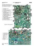


VYPER
™
VARIABLE SPEED DRIVE
OPERATION
100-200 IOM (FEB 09)
Page 42
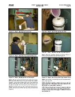
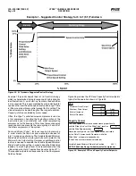
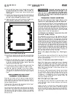
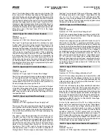
Example 1 - Suggested Control Strategy for 5 to 1 (5:1) Turndown
Example 1 (Figure 45) depicts the 5 to 1 (5:1) control strategy,
which is characterized by rapid response to highly dynamic
load fluctuations. A quick start-up from zero load condition
is also required. This is accomplished by programming total
speed control over the entire operational speed range. There
is little or no proportional control present for this setting. The
slide valve remains loaded throughout the range of operation.
Capacity is totally controlled by motor speed.
Often, the Vyper
™
controlled screw compressor is used as
a trim compressor, handling the fluctuating portion of the
load while used in combination with other reciprocating
compressors for the base load. This allows the required quick
response and also prevents the rapid cycling on and off of
the other compressors in the system.
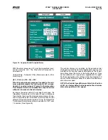
Some additional Vyper
™
features require programming
in order create the rapid response envelope needed for
5 to 1 turndown applications. The Variable Speed Minimum
Slide Valve Position is a factory default and is related to the
Minimum Drive Output setting. However, an additional control
feature is needed to override the Variable Speed Minimum
Slide Valve Position setting in order to keep the Slide Valve
loaded at a much higher level. Frick recommends that the
slide valve position for 5:1 applications be set as high as 97%.
The required setpoints are accessed from the Compressor
Safeties Screen.
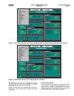
Figure 45 - 5:1 Turndown Suggested Control Strategy
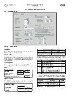
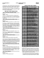
Figure 46 provides the VFD and Capacity Control setpoints
typical for the operation shown in Figure 45.
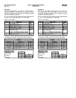
VFD
Maximum Drive Output
100%
Minimum Drive Output
20 %
Delay
Rate of Increase
12 %
1 SEC
Rate of Decrease
12 %
1 SEC
Capacity Control
The Drive Speed will increase and decrease proportionally
with the Slide Valve* until the Slide Valve* reaches
97 %
and the Drive Speed reaches
20 %
Above these setpoints, the Drive Speed will be controlled
by the Rate Of Increase and Decrease while the
Slide Valve* will operate independently.
*Slide Valve or other mechanical unloader
Variable Speed Minimum Slide Valve Position
40.0%
NOTE: Slide Valve Range limited to protect compressor
Figure 46 - Example 2 VFD and Capacity Control Setpoints
Содержание Vyper 254
Страница 17: ...VYPER VARIABLE SPEED DRIVE INSTALLATION 100 200 IOM FEB 09 Page 17 Liquid Cooled Vyper P I Diagram Economized...
Страница 26: ...VYPER VARIABLE SPEED DRIVE INSTALLATION 100 200 IOM FEB 09 Page 26 ANALOG BOARD WIRING Figure 21...
Страница 67: ...100 200 IOM FEB 09 Page 67 VYPER VARIABLE SPEED DRIVE NOTES...