Frick Vyper 254 Скачать руководство пользователя страница 11

VYPER

 VARIABLE SPEED DRIVE

INSTALLATION

100-200 IOM (FEB 09)

Page 11

Recommended Analog signal wire

0.750 mm2 (18AWG) twisted pair, 100% shield with drain.  

If the wires are short and contained within a cabinet which 

has no sensitive circuits, the use of shielded wire may not 

be necessary, but is always recommended.

Recommended Digital signal wire

Unshielded Per US NEC or applicable electrical code.

Shielded

0.750 mm2 (18AWG), 3 conductor, shielded.

TRANSFORMERS

In most installations the transformer that supplies the refrig-

eration equipment is the same transformer that powers most 

of the other loads in the same building. These transformers 

are generally very large relative to the refrigeration load.  

However is some case there will be an individual transformer, 

sized and dedicated to the refrigeration system alone. For 

example,  when  a  460 VAC VSD  is  used  and  the  existing 

power is 208V, a 208 V to 460V step-up transformer should 

be installed. 

Such  transformers  must  be  specially  sized  whenever  a 

Vyper

 is involved. Failure to properly size the transformer 

may result in unreliable operation. 

NOTE: Contact the fac-

tory or power provider for transformer sizing.
NOTE: Transformer must be K4 rated.

When  installing  a Vyper

  on  an  existing  transformer,  the 

total KVA requirement of the VSD controlled system and all 

branch circuits must be considered. The transformer sup-

plying the Vyper

 shall be sized such that the transformer 

voltage does not sag more than 5% when subjected to load 

excursions. The  steady-state  operating  voltage  should  be 

within the range of 414 to 508 VAC, 3 phase 60 Hz, or 342-

423 VAC, 3 phase, 50 Hz.

KVA

Impedance

Weight (lb)

175

5%-6%

1100

220

5%-6%

1470

275

5%-6%

1750

330

5%-6%

1990

440

5.5% - 6.5%

2700

550

5.5% - 6.5%

3100

660

5.5% - 6.5%

3600

750

6% - 7%

4600

880

6% - 7%

5300

990

6% - 7%

5800

1250

6.5% - 7.5%

6200

1500

6.5% - 7.5%

6800

1750

6.5% - 7.5%

7500

2000

6.5% - 7.5%

8200

Johnson  Controls  offers  a  line  of  Recommended Vyper 

VSD Transformers. These transformers have the following 

features:

•  Steel core for low flux density operation.
•  Standard K-4 rating. K-13, K-20, K-30 is available as an 

option.

•  UL / CSA certified.
•  600 Volt class
• 

Primary Voltage: 208V, 230V, 460V, 575V

•  Conductors, 40°C ambient
• 

Sinusoidal loading not to exceed K-4

• 

Secondary Voltage: 460

•  NEMA 2 housing
•  60 Hz, 150°C temperature rise, 220°C insulation
•  Taps: 1 plus, 1 minus@5%

POWER FACTOR CAPACITORS

Power factor correction capacitors are not required since the 

Vyper

 has a 0.95 minimum power factor at all operational 

loads and conditions. Capacitors can be located at one or 

several  places  on  a  distribution  system.  Solid-state  motor 

controllers  may  not  run,  or  have  difficulty  starting  in  that 

scenario. The degree of malfunction depends on the size of 

the capacitors, the distance away for the solid-state controls, 

and the size of the building supply transformer.

With a VSD there is no way to know in advance whether the 

capacitors will cause interference.  When a VSD is started and 

there are problems cause by power factor capacitors, it will be 

necessary to remove those capacitors. In some installations, 

capacitors are switched on line as power factor drops.  

The switching transients created by connecting and discon-

necting power factor capacitors may cause the Vyper

 to drop 

off-line. High voltage power factor capacitors may be located 

on the primary side of the transformer supplying power to 

the Vyper

 without causing any malfunction to equipment 

on the secondary side.

SOFT-START SEQUENCE

At start-up, both the motor and slide valve begin to load to 

a preset value.

NOTE: There is a 30 second delay at initial start-up to 

charge the capacitors of the Vyper

. This delay does not 

occur in Standby mode, only on initial start-up.

The Frick slide valve will load to the Variable Speed Minimum 

Slide Valve Position setpoint, and the Vyper accelerates to the 

speed corresponding to the Minimum Drive Output setpoint. 

From this point the slide valve position and motor speed are 

controlled by the Capacity Control setpoints.

During start-up, the VSD varies the voltage and frequency 

to maintain the same proportion that exists between the two 

at design conditions. The required inrush current to start the 

motor never exceeds the FLA rating of the given motor and is 

typically only 10-20% of FLA. Mechanical forces on the motor 

windings and motor heating are 20% to 50% lower than with 

a mechanical starter. This results in less mechanical shock 

to the system and longer motor life.

INTERFACING ElECTRICAl EQUIPMENT

There are many low voltage DC signals in the Vyper

 which 

may be picked up from other electrical devices or wiring in the 

vicinity of the electronic controls. It is essential that non-VSD 

wiring is not routed through the Vyper

 cabinet. It is equally 

important that no external equipment is tied to the Vyper


control wiring in any way. A control system should never be 

wired to the Vyper

 circuitry. Never use 120V supply to feed 

the VSD  control  wiring. The Vyper

  has  it’s  own  internal 

power  supply.  Using  an  external  supply  may  damage  the 

Vyper

 and may also cause hazardous working conditions 

for service and operating personnel. 

Содержание Vyper 254

Страница 1: ...3c THIS MANUAL CONTAINS RIGGING ASSEMBLY START UP AND MAINTENANCE INSTRUCTIONS READ THOROUGHLY BEFORE BEGINNING INSTALLATION FAILURE TO FOLLOW THESE INSTRUCTIONS COULD RESULT IN DAMAGE OR IMPROPER OPE...

Страница 2: ...IPMENT 11 INTERFERENCE WITH ELECTRONIC EQUIPMENT 12 SYSTEM OPERATING CONDITIONS 12 PNEUMATIC CONTROLS 12 VYPER SYSTEM OVERVIEW 12 CONFIGURATION 16 VYPER COOLING LOOP 16 Liquid Cooled Vyper P I Diagram...

Страница 3: ...ctronic con trol equipment All safety precautions consistent with opera tion of high current and voltage electrical equipment should be strictly enforced JOB INSPECTION Immediately upon arrival examin...

Страница 4: ...GING AND HANDLING The Vyper cabinet unit is best moved via lifting lugs on the top sides of the cabinet Special care must be exercised not to damage the pump or peripheral equipment on the rear of the...

Страница 5: ...and Frick publication S90 400 SB Verify that all control power 120 VAC communications analog wiring and 460 VAC power are in separate metallic con duits Properly shielded and grounded analog cables a...

Страница 6: ...e the tables in this manual to calculate what they should be 7 Verify proper operation of the motorized coolant mixing valve on the back of the drive Locate the Coolant mixing valve on the back of the...

Страница 7: ...operating frequency range of the drive The unit is started with the compressor fully unloaded until the frequency reaches the minimum operating frequency range In addition the drive is capable of ope...

Страница 8: ...0 feet Adequate service clearances including door swing must be maintained around the Vyper Care should be taken to ensure that the Vyper and it s associated piping and wiring do not obstruct the acce...

Страница 9: ...ER PRESSURE DROP In order to adequately size piping and booster pump require ments the pressure drop of the coolant across the heat Figure 3 Minimum Flow Rates GLYCOL exchanger must be known Figure 4...

Страница 10: ...tions regarding disconnect devices conductor sizes wire types and circuit protection Unshielded cable is acceptable if it can be separated from sensitive circuitry Allow a spacing of 12 inches for eve...

Страница 11: ...r at all operational loads and conditions Capacitors can be located at one or several places on a distribution system Solid state motor controllers may not run or have difficulty starting in that scen...

Страница 12: ...odes One SCR and one diode are contained in each module Three modules are required to covert the three phase input AC voltage to DC voltage 1SCR 3SCR The modules are mounted on a liquid cooled heatsin...

Страница 13: ...SPEED DRIVE INSTALLATION 100 200 IOM FEB 09 Page 13 Figure 6 Vyper Elementary Wiring Diagram NOTE Drawings for specific units can be found in the door of the Vyper drive or check with Frick Engineeri...

Страница 14: ...sure that the IGBT transistor module does not rupture if a failure were to occur on the DC link of the Filter Power Unit THETHREE PHASE INDUCTOR provides some impedance for the filter to work against...

Страница 15: ...VYPER VARIABLE SPEED DRIVE INSTALLATION 100 200 IOM FEB 09 Page 15 Figure 8 Harmonic Filter Elementary Wiring Diagram NOTE Typical Check with engineering for latest drawings...

Страница 16: ...nd shutdowns as sociated with theVyper coolant temperature reading These wil also be factory set for a Low Temp alarm and shutdown at 85 F and 80 F with a 90 second delay when running The High Temp Al...

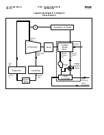
Страница 17: ...VYPER VARIABLE SPEED DRIVE INSTALLATION 100 200 IOM FEB 09 Page 17 Liquid Cooled Vyper P I Diagram Economized...

Страница 18: ...VYPER VARIABLE SPEED DRIVE INSTALLATION 100 200 IOM FEB 09 Page 18 Liquid Cooled Vyper P I Diagram Noneconomized...

Страница 19: ...The Vyper cabinet is mounted on a rectangular welded steel channel which provides both an attachment point for the cabinet s side brackets and also helps to maintain the rigidity of the cabinet durin...

Страница 20: ...Page 20 BLOWER MOTOR ROTATION The Blower Motor rotation is marked on the blower assembly and is to be such that the blower draws into the assemly through the screen and pushes down and through the mot...

Страница 21: ...Page 21 Dimensions in Inches Drive HP A B C D E F G H J K 305 254 1 63 4 50 9 00 6 38 4 38 35 00 5 50 3 56 6 63 2 00 437 362 6 63 6 75 10 13 2 00 3 25 40 53 2 25 3 00 13 00 2 00 Contact factory for de...

Страница 22: ...in that the Drive has been powered down for at least five minutes This allows the internal capacitors resistors to discharge the DC bus and allow for safe maintenance of the unit Failure to do so may...

Страница 23: ...ion 216 240 in lb ELECTRICAL CONDUITS All power wiring must be contained in metallic conduit All compressor motor wiring must be in a separate metallic conduit Oil pump motor wiring must be in a separ...

Страница 24: ...VYPER VARIABLE SPEED DRIVE INSTALLATION 100 200 IOM FEB 09 Page 24 MOTOR RTD THERMAL PROTECTION Figure 17 TEMPERATURE CONTROL VALVE WIRING Figure 18...

Страница 25: ...VYPER VARIABLE SPEED DRIVE INSTALLATION 100 200 IOM FEB 09 Page 25 MOTOR COOLING BLOWER WIRING Figure 19 Figure 20 DRAWING NOTES...

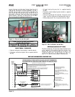
Страница 26: ...VYPER VARIABLE SPEED DRIVE INSTALLATION 100 200 IOM FEB 09 Page 26 ANALOG BOARD WIRING Figure 21...

Страница 27: ...ans c Confirm operation of coolant circulation pump d Confirm wiring and operation of the motor blower fans if present Mounting a Verify that the Vyper Drive is properly mounted to the floor or wall f...

Страница 28: ...proper electrical connections as discussed in previous sections The Vyper setup consists of three primary requirements Cooling Loop Fluid Preparation Quantum LX Panel Setup Job FLA Trim Pot Adjustment...

Страница 29: ...ntil the fluid level remains constant about one inch form the top of the manifold See Figure 30 Figure 30 Step 6 Top Off the Cooling System Figure 31 Step 7 Replace the Pipe Plug and Tighten Step 7 Re...

Страница 30: ...fferential pressure the motor speed will increase to meet the capacity requirement When the slide valve reaches the Capacity Control Slide Valve setpoint the motor speed can increase At this point the...

Страница 31: ...r can select either the Vyper or the Har monic Filter setup screens See Figure 35 The flydown menu allows the user to select either theVyper Drive setup or if the Harmonic Filter is installed the disp...

Страница 32: ...aring theVSD memory and resetting the kWh record Standby Time The VSD enters Standby mode when there is no load on the VSD The VSD capacitor banks remain charged and the compressor output is 0 Hz Stan...

Страница 33: ...indicate the status of the field They are displayed as the following 0 no off 1 yes on VSD Operating Mode Harmonic Filter Present Harmonic Filter Operating Mode Water Pump Energized Precharge Relay En...

Страница 34: ...ompressors via the SFS 229 Frick Interface Board This is accomplished through the reception of a Speed Command value in rotations per minute and a Run Command signal from the Quantum LX control panel...

Страница 35: ...on The screen shown in Figure 39 will appear Type 2 into the User Level field Enter Level 2 password Return to the menu and the Home screen The home screen will now provide additional information as s...

Страница 36: ...acity Regulations and Package spe cific information Verify that Screw Compressor with Vyper is selected under the package Drive field This will allow the Vyper specific screens to be displayed See Fig...

Страница 37: ...set to PID Channel 5 Use the table below to program the proper settings Parameter Value Name Drive Cooling Control Running Action Forward Control Point Vyper Coolant Device Source Analog Board 2 Devi...

Страница 38: ...ing the motor and the drive from high currents High Motor Amps Load Inhibit Force Unload Delay Warning 5 SEC Shutdown 5 SEC Applied Motor FLA Calculation IF USE Mtr Nameplate SF 1 0 Mtr Nameplate FLA...

Страница 39: ...Inhibit Applied Motor FLA x 1 1 374 A Force Unload Applied Motor FLA x 1 12 380 A Warning Applied Motor FLA x 1 13 384 A Shutdown Applied Mtr FLA x 1 15 391 A High Motor Amps Load Inhibit 357 Force U...

Страница 40: ...A Shutdown Applied Mtr FLA x 1 15 339 A High Motor Amps Load Inhibit 310 Force Unload 324 Delay Warning 330 5 SEC Shutdown 337 5 SEC Example 4 What are the High Motor Amp setpoints if a 437 HP Vyper...

Страница 41: ...Cycle Time settings and the maximum acceleration rate of 6 08 Hz sec Rate of Decrease The Rate of Decrease parameter set ting determines the speed change step size at which the Vyper will decelerate...

Страница 42: ...wn applications The Variable Speed Minimum Slide Valve Position is a factory default and is related to the Minimum Drive Output setting However an additional control feature is needed to override the...

Страница 43: ...en selecting Setpoints and Compressor Press the ENTER key to advance to the Compressor Safeties Screen Step 2 Refer to Figure 47 Use the cursor arrow and Tab keys to navigate to the Highest Capacity T...

Страница 44: ...re 48 This control strategy is a variation on the generic control strategy described previously Not all applications require or are suitable for the very low speeds obtainable by the Vyper drive Many...

Страница 45: ...proportional component over every 30 sec onds to drive the actual value back to the Capacity Control setpoint If the actual value remains 21 psig the Integration Time Setpoint would increase the drive...

Страница 46: ...2 Motor Service Factor 1 15 3 Multiply Line 1 x Line 2 4 HP Rating of Vyper Drive 5 Vyper Amp Limit If Line 4 is 305 254 HP Value is 380 A If Line 4 is 437 362 HP Value is 565 A 6 Multiply Line 5 x 1...

Страница 47: ...Closed 6 Open 1 Closed 5 Open 4 Open 3 Open Open 2 Open 1 Open FRICK INTERFACE BOARD DIP SWITCH SETTINGS Used before Jan 2008 On the Frick Interface Board Figure 54 on the Vyper right door there is a...

Страница 48: ...ndicators RX TX Logic Board to Quantum LX 8 J16 Communications Cable Logic Board to Quantum LX 9 Communications Indicators RX TX Logic Board to Filter Board 10 J15 Communications Cable Logic Board to...

Страница 49: ...he cooling system and oxidizing the aluminum If any of these conditions exist the coolant may have bacteria growth Take proper health precautions when draining the coolant Drain the coolant and blow t...

Страница 50: ...put current This is due to the power factor at the input to the Vyper being greater than 0 95 and nearly unity when the Harmonic filter option is included Motor FLA must be measured at the motor termi...

Страница 51: ...ick Vyper VYPER ALARMS SHUTDOWNS In addition to the Alarms and Shutdowns that the Quantum LX software generates for the basic compressor package there are warnings and shutdowns that are associated wi...

Страница 52: ...lt 9 Harmonic Filter Logic Board Or Comms Fault 10 Harmonic Filter High Total Demand Distortion 11 High Phase B Inverter Baseplate Temperature 12 High Phase C Inverter Baseplate Temperature 13 Low Pha...

Страница 53: ...ckground message when the chiller is running When this message is displayed all filter related values are unavailable If communications is reestablished normal values will again be displayed If this p...

Страница 54: ...r control board This board monitors the satura tion voltage drop across each IGBT while gated on If the IGBT s saturation voltage exceeds the prescribed limit the gate driver will make the determinati...

Страница 55: ...nput to the logic board can be checked across wires 219 and 220 of the J5 connector of the logic board This message usually means that power to the Vyper was removed If this was not the case check the...

Страница 56: ...24 in the Vyper cabinet Also check to ensure that the serial communications wiring between the micro board and the Interface board andVyper Logic board and the Interface board are connected properly...

Страница 57: ...addition if both temperatures fall below the 37 F limit the unit will trip and the fan s and water pump will be energized This feature provides the Service Dept with a means to run the water pump whi...

Страница 58: ...as Fault 51 except for applying to Phase B Fault 54 Harmonic Filter Phase Locked Loop Message Quantum Fault 54 Quantum LX Harmonic Filter Phase Locked Loop Fault This shutdown indicates that a circui...

Страница 59: ...DC below the filter DC link voltage setpoint The filter DC link voltage setpoint is determined by the filter logic board via the sensing of the three phase input line to line voltage This setpoint is...

Страница 60: ...t to the initial speed command and the Motor Current is monitored every two seconds If the Motor Current rises above 103 the unit enters current limit and a warning condition will be set Thereafter as...

Страница 61: ...RD 639A0211H25 FUSES VOLTAGE TRANSIENT BOARD 639A0211H26 SCR TRIGGER BD 60 HZ 639A0211H27 SCR TRIGGER BD 50 HZ 639A0211H28 VSD DC BALANCING RESISTOR 639A0211H29 COOLANT PUMP 639A0211H30 BUS SNUBBER CA...

Страница 62: ...HZ 639A0211H27 SCR TRIGGER BD 50 HZ 639A0211H28 VSD DC BALANCING RESISTOR 639A0211H29 COOLANT PUMP 639A0211H30 BUS SNUBBER CAPACITOR 639A0211H31 SNUBBER RESISTOR 639A0211H32 SHELL TUBE HEAT EXCHANGER...

Страница 63: ...FILTER RETROFIT 50HZ 639A0211H59 FILTER POWER MODULE COMPLETE KIT 639A0211H66 HARMONIC FILTER SPARE PARTS LISTS1 MODEL 437 Part Description Frick Part BUS ISOLATOR BOARD 639A0211H42 BUS PLATE KIT 639...

Страница 64: ...gh DC Bus Voltage 58 Harmonic Filter Precharge Low DC Bus Voltage 58 Harmonic Filter Run Signal 59 Harmonic Filter Serial Communication 60 High Converter Heat Sink Temperature 56 High DC Current Bus V...

Страница 65: ...URE CONTROL VALVE WIRING 24 transducers 10 WIRING ENTRY LOCATIONS 21 Insulated Gate Bipolar Transistor 12 Integration Time Setpoint 45 Interface board 53 inverter module base plate 56 J Job FLA 46 57...

Страница 66: ...upply Contactor 34 Supply Current 33 Total Demand Distortion 33 Total Harmonic Distortion 33 Total kWh 33 Vyper Level 2 Screen 47 Vyper Level 2 screen 46 Vyper Amp Limit 40 Quantum LX Control panel 3...

Страница 67: ...100 200 IOM FEB 09 Page 67 VYPER VARIABLE SPEED DRIVE NOTES...

Страница 68: ...System integration is what we do Q NET supports open protocols for SCADA systems i e Allen Bradley DF1 Modbus RTU Modbus ASCII and Industrial Ethernet Protocols Q NET connects instantly for local or...

Отзывы: