


VYPER
™
VARIABLE SPEED DRIVE
INSTALLATION
100-200 IOM (FEB 09)
Page 16
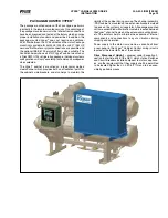
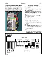
THE “TRAP” FIlTER
is standard on all Frick Vyper
™
units
that contain the Harmonic Filter. The trap filter is composed
of a series of capacitors, inductors, and resistors. The trap
filter is used to reduce the effects of the PWM switching
frequency of the filter (20kHz) on the AC line.
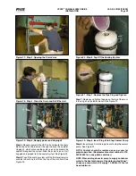
CONFIGURATION:
The Frick Vyper
™
is internally cooled with a factory calibrated
liquid cooling circuit which offers many advantages over tradi-
tional air-cooled systems. The liquid circuit provides precisely
controlled coolant temperatures to the heat generating com-
ponents and delivers coolant into locations that no air-over
fan could penetrate. The Vyper
™
liquid-cooling arrangement
performs independently of fluctuating ambient conditions. The
NEMA 4 Indoor-rated cabinet seals the internal electronics
and piping from corrosive refrigerant vapors while provid-
ing superior cooling for the internal electronic components.
Efficient liquid cooling also allows for smaller cabinet size
and longer component life than traditional air-cooled units.
Either plant condenser water or a facility supplied Glycol loop
subsequently removes the heat in the coolant via the heat
exchanger located at the back of the cabinet.
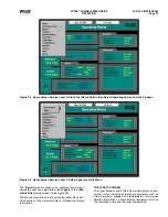
VYPER
™
COOlING lOOP
While the compressor is running, the Quantum
™
LX control
panel monitors the temperature of Vyper
™
drive coolant. With
this information, the Quantum
™
LX delivers a 4-20 mA signal
to the 3-way mixing valve, based on the setpoints of a PID
loop output from the Quantum
™
LX. This signal will maintain
the Vyper
™
coolant temperature at the control setpoint for
the PID loop. This setpoint will be set at 110°F at the factory.
There are also low and high temp alarms and shutdowns as-
sociated with the Vyper
™
coolant temperature reading. These
wil also be factory set for a Low Temp. alarm and shutdown
at 85°F and 80°F with a 90 second delay, when running.
The High Temp. Alarm and shutdown will be factory set at
125°F and 130°F with a 30 second delay when running. If
the Vyper
™
coolant temperature drops too low, condensation
may occur, damaging vital electronic components.In addi-
tion to controlling the Vyper
™
cabinet cooling system, the
Quantum
™
LX panel also monitors four temperatures from
the Vyper
™
cabinet. If any of these temperatures rise too
high, the Quantum
™
LX panel will go to a Stop Load condi-
tion, preventing either the slide valve position or motor speed
from increasing. If the temperature continues to rise, the
Quantum
™
LX panel will next go to a Force Unload condition.
In this situation, the slide valve will unload to lower the motor
torque required, in an effort to drop the temperature in the
panel. Below is a chart showing the Stop Load and Force
Unload temperatures as well as the temperatures where the
Vyper
™
cabinet will automatically shut down.
location
Stop Start Force Unload Shutdown
Base plate
Temp Converter
160°F
165°F
175°F
Heat Sink Temp
155°F
160°F
170°F
Harmonic Filter
130°F
135°F
145°F
Base plate Temp
160°F
165°F
175°F
VYPER
™
CONFIGURATIONS - liquid Cooled
HP
Freq
A
B
C
D
E
F
G
H
J
K
l
M
N
254
50
51
42.5
4.25
47
51
5.5
17
36
70
22.5
20.4
16.4
2
305
60
51
42.5
4.25
47
51
5.5
17
36
70
22.5
20.4
16.4
2
362
50
58
49.5
4.25
54
58
5.5
19.1
41
75
24.6
22.5
18.5
2
437
60
58
49.5
4.25
54
58
5.5
19.1
41
75
24.6
22.5
18.5
2
Remote-mounted configuration is shown. Pack-
age-mount dimensions are identical except for
the elimination of the stand. Coolant connections
to the Heat Exchanger are 1½ NPT.
NOTE: Considering all applicable codes regarding
spacing and clearance, be sure to provide adequate
space behind the drive for servicing the cooling
circuit (recommended 18” minimum).
Содержание Vyper 254
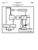
Страница 17: ...VYPER VARIABLE SPEED DRIVE INSTALLATION 100 200 IOM FEB 09 Page 17 Liquid Cooled Vyper P I Diagram Economized...
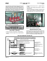
Страница 26: ...VYPER VARIABLE SPEED DRIVE INSTALLATION 100 200 IOM FEB 09 Page 26 ANALOG BOARD WIRING Figure 21...
Страница 67: ...100 200 IOM FEB 09 Page 67 VYPER VARIABLE SPEED DRIVE NOTES...