


Table of contents
3QLCLM
Edition: 04/2014
29
6.0 Assembly
6.1
Actions to be taken before assembly
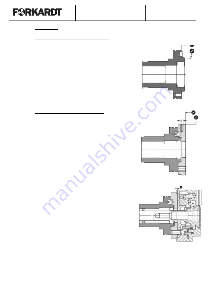
6.1.1 Checking the spindle nose
of the chuck flange
The mounting surfaces on the spindle nose have to be
checked with a dial gage to ensure that high accuracy in
respect of radial run-out of the power chuck is achieved
Radial run-out of
register:
max. 0,005 mm
Axial run-out of the register:
max. 0.005 mm
• The flatness of the face has to be checked with a straight
edge.
• The surface of the face has to be clean and the holes in it
must be deburred.
6.1.2 Checking the fitted mounting flange
The power chuck has a central register. An appropriate
mounting flange (see also Section 5.8.1) is attached to the
spindle nose of the lathe for direct mounting of the power
chuck on the machine spindle with short taper to DIN, ISO and
ASA standards.
If the adapter flange is manufactured by the user, it must be
finish-turned on the machine spindle and balanced before the
power chuck is mounted.
After fitting of the mounting flange, the radial and axial run-out
must be checked!
•
Remove dirt or chips from machine spindle. Clean the
centering collar and locating face of the adapter flange.
•
The flatness of the face has to be checked with a straight
edge.
•
The tapped holes for the mounting bolts must be
countersunk, so that the thread is not stripped.
•
The mounting surface for the power chuck must not be
concave or convex.
•
The flange must be in contact over the whole surface!
Wrong!


